Thermodynamic Machines
Storyboard 
The thermodynamic machine was first analyzed by Sadi Carnot who in 1824 published his 'Reflections sur la Puissance Matrice du Feu sur les Machines' analyzes how heat can be used to perform work. In principle it is the application of the first law of thermodynamics in which a system in a system circulates heat so that a fraction becomes work. The fraction is called the efficiency of the machine and by the second law of thermodynamics it is limited and all heat cannot be converted to work.
ID:(1484, 0)
Graphical representation of the effective work obtained
Definition 
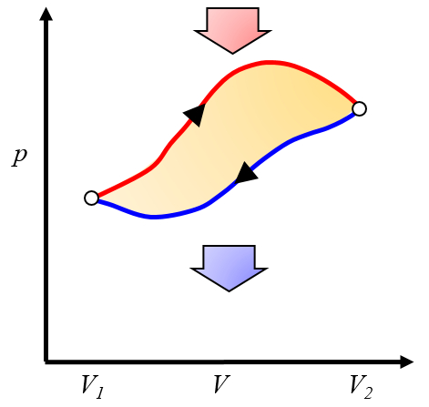
The net work obtained is the difference between the work obtained and the work required to complete the cycle:
ID:(10268, 0)
Graphical representation of the work obtained
Image 
Since the work is
| $ \delta W = p dV $ |
it can be represented on a pressure versus volume graph as the area under the pressure curve as a function of volume:
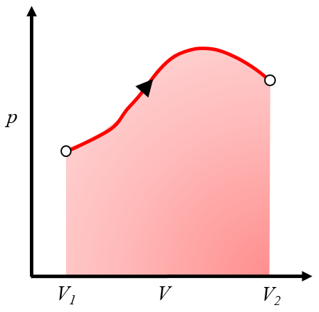
This area represents the work obtained when a gas performs work by expanding from volume $V_1$ to volume $V_2$.
Typically, this process is achieved by heating the system, causing it to expand and perform the work. An example would be a piston with gas heated in a boiler.
ID:(10266, 0)
Graphical representation of the work to be invested
Note 
To repeat the process, one must return from volume $V_2$ to volume $V_1$, which means following a curve in the pressure versus volume diagram in the opposite direction:
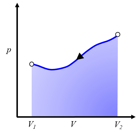
This represents work that needs to be invested, and we must supply it to repeat the cycle.
Typically, this process is achieved by cooling the system, causing it to contract. The energy to be invested corresponds to the heat removed from the system.
ID:(10254, 0)
Carnot cycle: scheme of a machine
Equation 
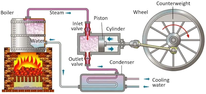
In a machine that utilizes the Carnot concept, the following processes take place:
• The reservoir with the higher temperature is created using a furnace.
• The reservoir with the lower temperature is created using a refrigeration system.
• The generated vapor from the reservoir expands into a gas, displacing the piston and raising the compensating mass. In the first isothermal stage, the first valve is open while the second valve is closed. In the second stage of the process, the first valve is closed, and the expansion continues adiabatically.
• In the third stage, the second valve is opened, and with the help of the compensating mass, the piston is returned, and the gas is expelled isothermally. In the fourth stage, the valve is closed, and the process concludes adiabatically.
ID:(11134, 0)
Carnot cycle
Script 
Sadi Carnot introduced [1] the theoretical concept of the first machine design capable of generating mechanical work based on a heat gradient. This concept is realized through a process in the pressure-volume space where heat is added and extracted, as depicted in the image:
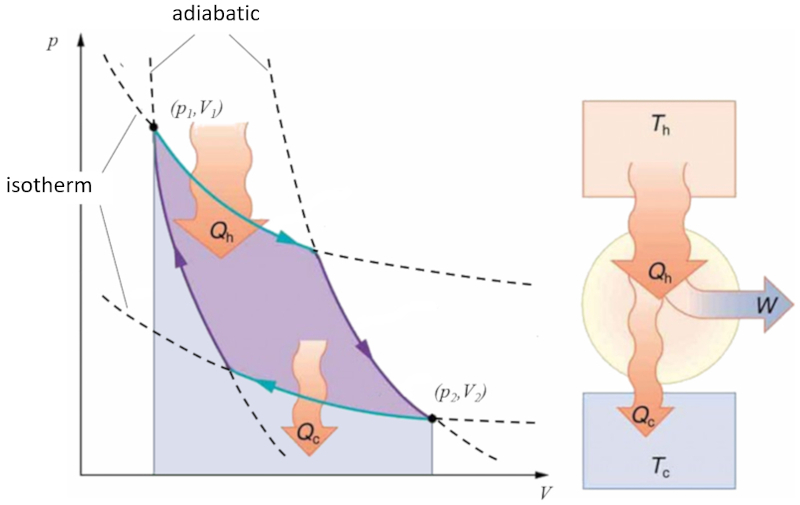
The area under curve the heat supplied ($Q_H$), spanning from 1 to 2, represents the energy input required to transition from state ($p_1, V_1$) to state ($p_2, V_2$). Conversely, the area under curve the absorbed heat ($Q_C$), going from 2 to 1, represents the energy extraction needed to return from state ($p_2, V_2$) back to state ($p_1, V_1$). The difference between these areas corresponds to the region enclosed by both curves and represents the effective work ($W$) that the system can perform.
Carnot also demonstrated that, in accordance with the second law of thermodynamics, the heat supplied ($Q_H$) cannot equal zero. This implies that no machine can convert all heat into work.
![]() [1] "Réflexions sur la puissance motrice du feu et sur les machines propres à développer cette puissance" (Reflections on the Motive Power of Fire and on Machines Fitted to Develop That Power), Sadi Carnot, Annales scientifiques de lÉ.N.S. 2e série, tome 1, p. 393-457 (1872)
[1] "Réflexions sur la puissance motrice du feu et sur les machines propres à développer cette puissance" (Reflections on the Motive Power of Fire and on Machines Fitted to Develop That Power), Sadi Carnot, Annales scientifiques de lÉ.N.S. 2e série, tome 1, p. 393-457 (1872)
ID:(11131, 0)
Carnot cycle for refrigeration
Variable 
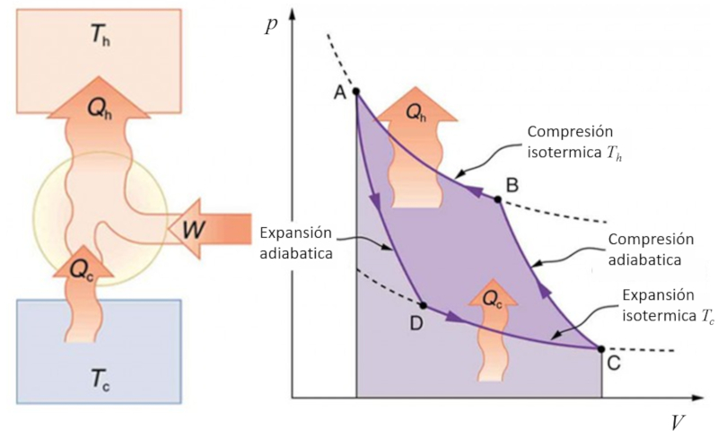
If the Carnot process is reversed, it can be used to transfer heat using work, which is known as a heat pump. In this case, the diagram is as follows:
ID:(11143, 0)
