
Control, use of lift
Image 
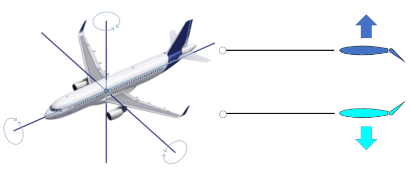
The ailerons are parts of the wings that allow their trailing edge to be curved upwards (generating downward force) or downwards (generating upward force). They are all positioned at points away from the center of mass to achieve a greater distance and therefore a higher torque, making them more effective in rotation.
Due to the geometry, there are three axes around which the aircraft rotates. The rudder aileron generates rotation around a vertical axis. The ailerons on the smaller rear wings (known as stabilizers) enable rotation around an axis perpendicular to the aircraft's axis, allowing for raising and lowering the nose of the aircraft. Lastly, there are the ailerons on the main wings that allow the aircraft to rotate around its central axis.
There is a type of aileron that is additionally extendable on the main wings near the fuselage, known as flaps, which increase/reduce both the wing area and the angle of attack.
Finally, there are surfaces that can be raised to disrupt the airflow over the wing and are used for braking, known as spoilers.
ID:(11081, 0)
Pitch control
Note
To pitch the aircraft's nose up or down, the elevators are used. Both elevators are employed in a symmetrical manner to generate a the force in the elevators ($F_e$) symmetric effect. Placing them at the tail of the aircraft achieves ERROR:10215.1 greater effectiveness by locating them near the center of mass. This provides sufficient control to raise or lower the aircraft's nose.
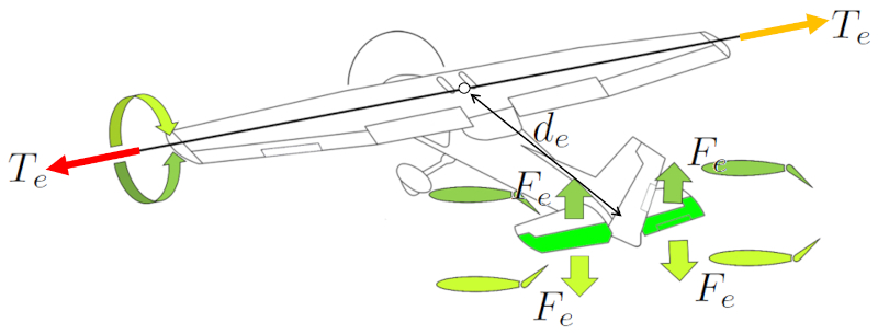
In older aircraft, control of the rear ailerons is achieved through a control stick, where pushing forward causes the aircraft's nose to descend, and pulling backward raises the nose. In Airbus family aircraft, this control is accomplished using a joystick.
In the case of birds, a similar solution exists, although in this case, the tail is not interrupted by a rudder.
ID:(15161, 0)

Roll control
Exercise
To perform a roll about its axis, the aircraft uses the ailerons. These generate a a force on the ailerons ($F_a$) which, in combination with a distance center of mass and ailerons ($d_a$), induces a a torque generated by the ailerons ($T_a$). The ailerons are located at the tips of the aircraft's wings to maximize their the distance center of mass and ailerons ($d_a$) relative to the center of mass and achieve greater a distance center of mass and elevators ($d_e$).
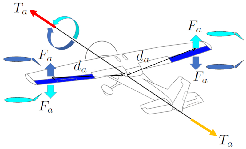
The ailerons operate asymmetrically, meaning that if the right wing's aileron generates upward lift, the left wing's aileron does the opposite, and vice versa. This way, these forces generate a torque that allows the aircraft to turn clockwise or counterclockwise.
The goal of the rotation is to generate, with the lift force, a force orthogonal to the central axis, resulting in a curve in the aircraft. This reinforces the action of the rudder, assisting in the aircraft's turning maneuver. In fact, this is how birds perform their turning maneuvers, as they do not have a rudder.
To execute the turning maneuver, the pilot uses the control column, which has a type of steering wheel that turns in the same direction as the aircraft. In other cases, such as with the joysticks in Airbus aircraft, there is no steering wheel, and the joystick is tilted in the desired direction to make the turn.
One of the challenges when performing a rotation around the aircraft's central axis is that the lift force is used to deviate the trajectory, resulting in a decrease in lift. This means that during a turning maneuver, the aircraft and bird tend to lose altitude unless power is increased.
ID:(15160, 0)

Yaw control
Script
To perform turns in an aircraft, the rudder is used. It generates a force on the rudder ($F_r$), which, combined with a center of mass and rudder distance ($d_r$), induces a force on the rudder ($F_r$). The rudder is located at the tail of the aircraft to maximize the center of mass and rudder distance ($d_r$) and achieve a greater a force on the rudder ($F_r$).
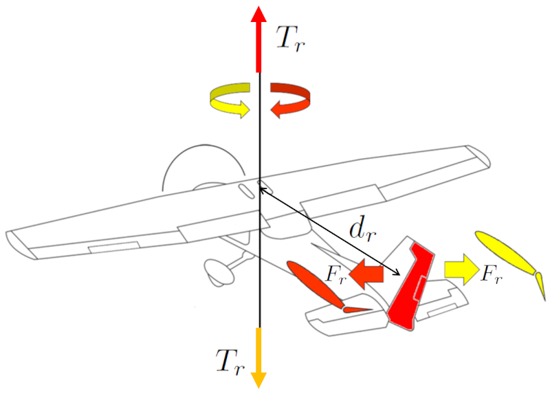
The pilot controls this movement using the pedals. The direction of the turn is determined by the pedal's direction.
ID:(15162, 0)
