Laminar flow
Storyboard 
In case the Reynold number is very small the flow is laminar. This shows that the flow can be represented as a series of sheets without the appearance of whirlpools and that it adapts to the edge conditions and flows harmoniously.
ID:(879, 0)
Laminar flow, ink
Definition 
One effective way to demonstrate laminar flow is by injecting ink into a flow using a thin needle that does not disturb it. This technique allows for a clear visualization of fluid layers sliding without mixing with each other. The ink disperses in the fluid in an orderly manner, creating distinct lines that reveal the direction and pattern of laminar flow. This method is widely used in experiments and demonstrations to visually illustrate the characteristics and properties of laminar flow in a visually impactful way.

ID:(7059, 0)
Laminar flow images
Image 
The observation in the laboratory demonstrates how ink creates a line (in this case, red). When the experiment is repeated at different positions, a pattern of layers becomes evident, indicating laminar flow.
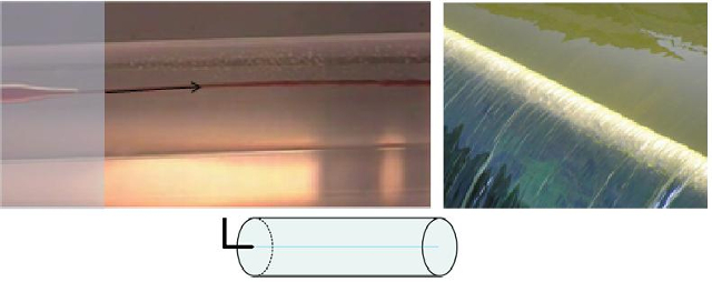
Liquids flowing in a laminar manner exhibit a smooth channel without the presence of eddies or abrupt lateral movements.
ID:(7060, 0)
Laminar flow around a sphere
Note 
An example of laminar flow around a sphere demonstrates that the layers of fluid move while maintaining their parallelism.
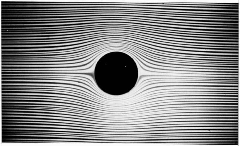
Here is an image depicting the calculation of flow between two plates and a sphere/cylinder (link to the image: http://luxsignifer.blogspot.com/2016/10/hele-shaw-flow-past-circle.html).
This situation occurs when the Reynolds number $Re$ is less than 5.
ID:(1889, 0)
Honey flow
Quote 
There are liquids that exhibit a peculiar behavior, as they seem to flow in slow motion. A classic example of this phenomenon is honey.
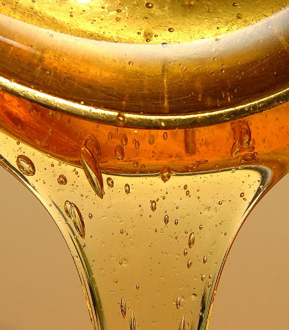
The underlying cause of this behavior is the viscous force that is generated when a layer of liquid slides or moves relative to its adjacent layers. This viscous force is proportional to the velocity variation between the liquid layers divided by the thickness of the layer under consideration.
ID:(1655, 0)
Laminars in the stream
Exercise 
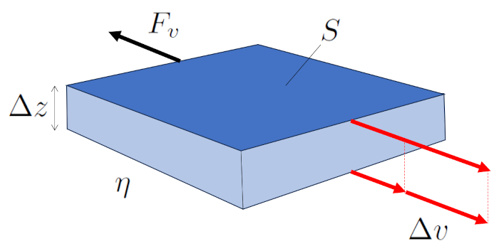
In laminar flow, adjacent layers move, and there exists a force generated by viscosity between them. The faster layer drags its slower neighbor, while the slower one restricts the advancement of the faster one.
Therefore, the force the viscose force ($F_v$) generated by ERROR:10119.1 over the other is a function of ERROR:5556.1, ERROR:5436.1, and ERROR:5422.1, as depicted in the following equation:
| $ F_v =- S \eta \displaystyle\frac{ \Delta v }{ \Delta z }$ |
illustrated in the following diagram:
ID:(7053, 0)
Flow through a cylinder
Equation 
Laminar flow around a cylinder can be represented as multiple cylindrical layers sliding under the influence of adjacent layers. In this case, the viscose force ($F_v$) with the tube length ($\Delta L$), the viscosity ($\eta$), and the variables the cylinder radial position ($r$) and the speed on a cylinder radio ($v$) is expressed as:
| $ F_v =-2 \pi r \Delta L \eta \displaystyle\frac{ dv }{ dr }$ |
The layer at the boundary at ERROR:5417.1 remains stationary due to the boundary effect and, through the viscosity ($\eta$), slows down the adjacent layer which does have velocity.
The center is the part moving at the maximum flow rate ($v_{max}$), dragging the surrounding layer. In turn, this layer drags the next one, and so on until reaching the layer in contact with the cylinder wall, which is stationary.
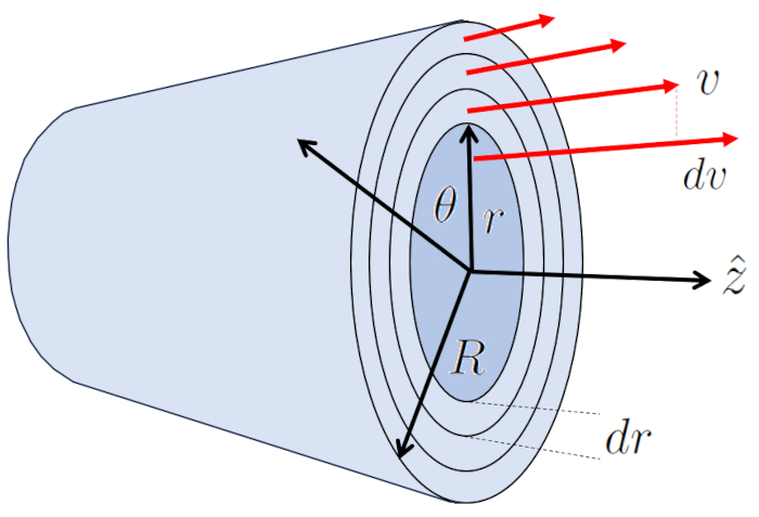
Thus, the system transfers energy from the center to the wall, generating a velocity profile represented by:
| $ v = v_{max} \left(1-\displaystyle\frac{ r ^2}{ R ^2}\right)$ |
with:
| $ v_{max} =-\displaystyle\frac{ R ^2}{4 \eta }\displaystyle\frac{ \Delta p }{ \Delta L }$ |
ID:(7057, 0)
Laminar flow
Description 
In case the Reynold number is very small the flow is laminar. This shows that the flow can be represented as a series of sheets without the appearance of whirlpools and that it adapts to the edge conditions and flows harmoniously.
Variables
Calculations
Calculations
Equations
As the viscous force is
| $ F_v =- S \eta \displaystyle\frac{ \Delta v }{ \Delta z }$ |
and the surface area of the cylinder is
$S=2\pi R L$
where $R$ is the radius and $L$ is the length of the channel, the viscous force can be expressed as
| $ F_v =-2 \pi r \Delta L \eta \displaystyle\frac{ dv }{ dr }$ |
where $\eta$ represents the viscosity and $dv/dr$ is the velocity gradient between the wall and the flow.
(ID 3623)
Examples
One effective way to demonstrate laminar flow is by injecting ink into a flow using a thin needle that does not disturb it. This technique allows for a clear visualization of fluid layers sliding without mixing with each other. The ink disperses in the fluid in an orderly manner, creating distinct lines that reveal the direction and pattern of laminar flow. This method is widely used in experiments and demonstrations to visually illustrate the characteristics and properties of laminar flow in a visually impactful way.

(ID 7059)
The observation in the laboratory demonstrates how ink creates a line (in this case, red). When the experiment is repeated at different positions, a pattern of layers becomes evident, indicating laminar flow.

Liquids flowing in a laminar manner exhibit a smooth channel without the presence of eddies or abrupt lateral movements.
(ID 7060)
An example of laminar flow around a sphere demonstrates that the layers of fluid move while maintaining their parallelism.

Here is an image depicting the calculation of flow between two plates and a sphere/cylinder (link to the image: http://luxsignifer.blogspot.com/2016/10/hele-shaw-flow-past-circle.html).
This situation occurs when the Reynolds number $Re$ is less than 5.
(ID 1889)
There are liquids that exhibit a peculiar behavior, as they seem to flow in slow motion. A classic example of this phenomenon is honey.

The underlying cause of this behavior is the viscous force that is generated when a layer of liquid slides or moves relative to its adjacent layers. This viscous force is proportional to the velocity variation between the liquid layers divided by the thickness of the layer under consideration.
(ID 1655)
In laminar flow, adjacent layers move, and there exists a force generated by viscosity between them. The faster layer drags its slower neighbor, while the slower one restricts the advancement of the faster one.
Therefore, the force the viscose force ($F_v$) generated by ERROR:10119.1 over the other is a function of ERROR:5556.1, ERROR:5436.1, and ERROR:5422.1, as depicted in the following equation:
| $ F_v =- S \eta \displaystyle\frac{ \Delta v }{ \Delta z }$ |
illustrated in the following diagram:

(ID 7053)
The viscose force ($F_v$) can be calculated from the parallel surfaces ($S$), the viscosity ($\eta$), the speed difference between surfaces ($\Delta v$), and the distance between surfaces ($\Delta z$) using the following method:
| $ F_v =- S \eta \displaystyle\frac{ \Delta v }{ \Delta z }$ |
(ID 3622)
Laminar flow around a cylinder can be represented as multiple cylindrical layers sliding under the influence of adjacent layers. In this case, the viscose force ($F_v$) with the tube length ($\Delta L$), the viscosity ($\eta$), and the variables the cylinder radial position ($r$) and the speed on a cylinder radio ($v$) is expressed as:
| $ F_v =-2 \pi r \Delta L \eta \displaystyle\frac{ dv }{ dr }$ |
The layer at the boundary at ERROR:5417.1 remains stationary due to the boundary effect and, through the viscosity ($\eta$), slows down the adjacent layer which does have velocity.
The center is the part moving at the maximum flow rate ($v_{max}$), dragging the surrounding layer. In turn, this layer drags the next one, and so on until reaching the layer in contact with the cylinder wall, which is stationary.

Thus, the system transfers energy from the center to the wall, generating a velocity profile represented by:
| $ v = v_{max} \left(1-\displaystyle\frac{ r ^2}{ R ^2}\right)$ |
with:
| $ v_{max} =-\displaystyle\frac{ R ^2}{4 \eta }\displaystyle\frac{ \Delta p }{ \Delta L }$ |
(ID 7057)
In the case of a cylinder, the surface is defined by ERROR:5430,0, and by the perimeter of each of the internal cylinders, which is calculated by multiplying $2\pi$ by the radius of position in a tube ($r$). With this, the cylinder resistance force ($F_v$) is calculated using the viscosity ($\eta$) and the variation of speed between two radii ($dv$) for the width of the cylinder the radius variation in a tube ($dr$), resulting in:
| $ F_v =-2 \pi r \Delta L \eta \displaystyle\frac{ dv }{ dr }$ |
(ID 3623)
ID:(879, 0)
