
Roll control
Storyboard 
Roll control is the mechanism that allows the aircraft to rotate around its longitudinal axis, raising one wing while lowering the other. This control is achieved by generating a difference in lift through the ailerons, which are located at the wingtips. This difference in lift creates a torque, responsible for causing the aircraft to roll around an imaginary axis along its fuselage, known as the roll axis.
ID:(2114, 0)
Roll control
Concept
To perform a roll about its axis, the aircraft uses the ailerons. These generate a a force on the ailerons (F_a) which, in combination with a distance center of mass and ailerons (d_a), induces a a torque generated by the ailerons (T_a). The ailerons are located at the tips of the aircraft's wings to maximize their the distance center of mass and ailerons (d_a) relative to the center of mass and achieve greater a distance center of mass and elevators (d_e).
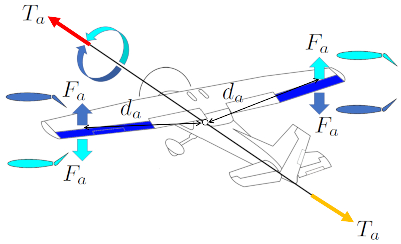
The ailerons operate asymmetrically, meaning that if the right wing's aileron generates upward lift, the left wing's aileron does the opposite, and vice versa. This way, these forces generate a torque that allows the aircraft to turn clockwise or counterclockwise.
The goal of the rotation is to generate, with the lift force, a force orthogonal to the central axis, resulting in a curve in the aircraft. This reinforces the action of the rudder, assisting in the aircraft's turning maneuver. In fact, this is how birds perform their turning maneuvers, as they do not have a rudder.
To execute the turning maneuver, the pilot uses the control column, which has a type of steering wheel that turns in the same direction as the aircraft. In other cases, such as with the joysticks in Airbus aircraft, there is no steering wheel, and the joystick is tilted in the desired direction to make the turn.
One of the challenges when performing a rotation around the aircraft's central axis is that the lift force is used to deviate the trajectory, resulting in a decrease in lift. This means that during a turning maneuver, the aircraft and bird tend to lose altitude unless power is increased.
ID:(15160, 0)

Moment of inertia for rolling
Description
The moment of inertia axis of the plane (I_a) can be approximated as the moment of inertia of a rectangular parallelepiped representing the aircraft's wing, rotating around an axis parallel to its width:
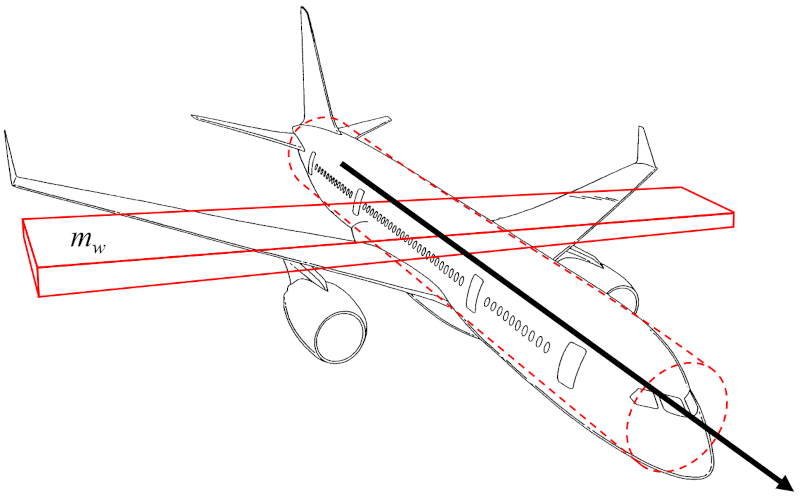
Since the aircraft's body is relatively narrow, the moment of inertia of the cylindrical body can be neglected as a first approximation. As a result, the moment of inertia axis of the plane (I_a) is proportional to the wing mass (m_w) and the square of the wing span (L).
Therefore, the moment of inertia axis of the plane (I_a) is calculated using the wing mass (m_w) and the wing span (L) as follows:
ID:(15992, 0)
Wing mass
Description
The wing mass (m_w) can be approximated as the volume of a rectangular parallelepiped multiplied by the density of the aircraft:
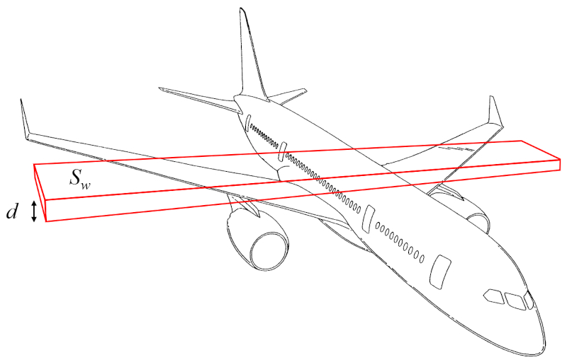
The volume can thus be calculated from the surface that generates lift (S_w) and the wing height (d).
Therefore, the wing mass (m_w) is determined using the aircraft body density (\rho_a), the surface that generates lift (S_w), and the wing height (d), as follows:
| m_w = \rho_a S_w d |
ID:(15989, 0)
Force generated by rolling
Equation
ID:(15164, 0)
Rolling torque
Equation
ID:(15167, 0)
Lift force
Equation
To generate higher pressure below than above the wing and generate lift, Bernoulli's principle is employed, correcting for the lack of energy density conservation using ($$). The pressure over the wing, the lift force (F_L), can be estimated using the density (\rho), the surface that generates lift (S_w), the coefficient of lift (C_L), and the speed with respect to the medium (v) through the following formula:
The lift force (F_L), along with the wing span (L), the density (\rho), the wing top speed factor (c_t), the wing bottom speed factor (c_b), the upper wing length (l_t), the bottom wing length (l_b), and the speed with respect to the medium (v), is found in
| F_L = \rho L ( c_b l_b - c_t l_t ) v ^2 |
If we consider the surface that generates lift (S_w), given by the wing span (L), the upper wing length (l_t), and the bottom wing length (l_b),
| S_w = \displaystyle\frac{1}{2} L ( l_t + l_b ) |
and for the coefficient of lift (C_L), defined as
| C_L = 4\displaystyle\frac{ c_t l_t - c_b l_b }{ l_t + l_b } |
we obtain
| F_L =\displaystyle\frac{1}{2} \rho S_w C_L v ^2 |
ID:(4417, 0)
Lift constant
Equation
From measurements, it is concluded that the lift coefficient C_L is proportional to the angle of attack \alpha:
After a certain angle, the curve decreases until it reaches zero. This is because beyond that critical angle, the vortices fully cover the upper surface of the wing, leading to a loss of lift. This phenomenon is known as \"stall\".
ID:(4441, 0)
Moment of inertia for rolling
Equation
The moment of inertia axis of the plane (I_a) is calculated from the wing mass (m_w) and the wing span (L), as follows:
ID:(15986, 0)
Wing mass
Equation
The wing mass (m_w) is calculated from the aircraft body density (\rho_a), the surface that generates lift (S_w), and the wing height (d), as follows:
ID:(15984, 0)
Aileron force arm
Equation
The distance center of mass and ailerons (d_a) is defined as half of the wing span (L), expressed as follows:
ID:(15995, 0)
Thickness to span ratio
Equation
The thickness to span ratio (\gamma_d) is defined as the ratio of the wing height (d) to the wing span (L), represented as follows:
ID:(15976, 0)