
Yaw control
Storyboard 
Yaw control is the mechanism that allows the aircraft to rotate around its vertical axis, turning the aircraft to the right or left. This control is achieved by deflecting the rudder, located at the tail of the aircraft. By moving the rudder, a lateral force is generated, creating a torque that causes the aircraft to rotate around an imaginary axis perpendicular to the fuselage, known as the yaw axis.
ID:(2115, 0)
Yaw control
Concept
To perform turns in an aircraft, the rudder is used. It generates a force on the rudder (F_r), which, combined with a center of mass and rudder distance (d_r), induces a force on the rudder (F_r). The rudder is located at the tail of the aircraft to maximize the center of mass and rudder distance (d_r) and achieve a greater a force on the rudder (F_r).
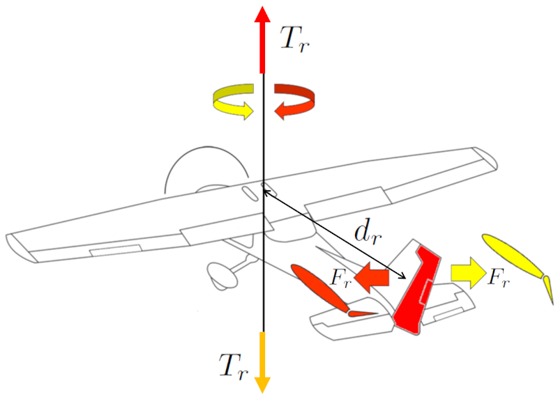
The pilot controls this movement using the pedals. The direction of the turn is determined by the pedal's direction.
ID:(15162, 0)
Wing mass
Description
The wing mass (m_w) can be approximated as the volume of a rectangular parallelepiped multiplied by the density of the aircraft:
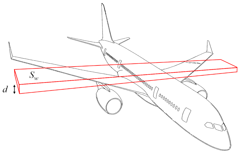
The volume can thus be calculated from the surface that generates lift (S_w) and the wing height (d).
Therefore, the wing mass (m_w) is determined using the aircraft body density (\rho_a), the surface that generates lift (S_w), and the wing height (d), as follows:
| m_w = \rho_a S_w d |
ID:(15989, 0)

Aircraft body mass
Description
The aircraft body mass (m_p) can be approximated as the volume of a cylinder multiplied by the density of the aircraft:
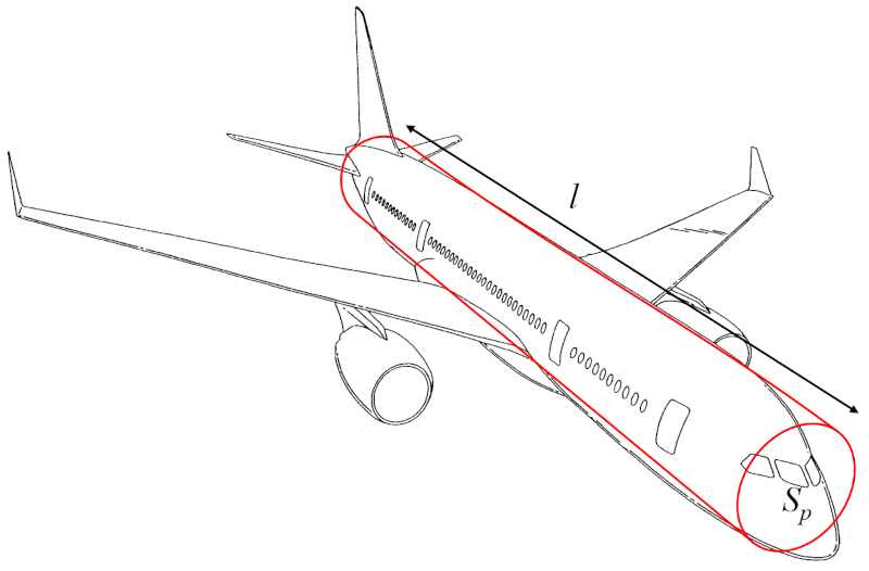
The volume can thus be calculated using the total object profile (S_p) (the radius or diameter) and the distance along the wing (l) (the height of the cylinder).
Therefore, the aircraft body mass (m_p) is determined from the aircraft body density (\rho_a), the total object profile (S_p), and the distance along the wing (l), as follows:
| m_p = \rho_a S_p l |
ID:(15990, 0)
Moment of inertia for yaw
Description
The vertical axis moment of inertia (I_r) can be approximated as the sum of the moment of inertia of a cylinder representing the aircraft fuselage, rotating around an axis perpendicular to its longitudinal axis, and the moment of inertia of a rectangular parallelepiped representing the wings, rotating around an axis perpendicular to them:
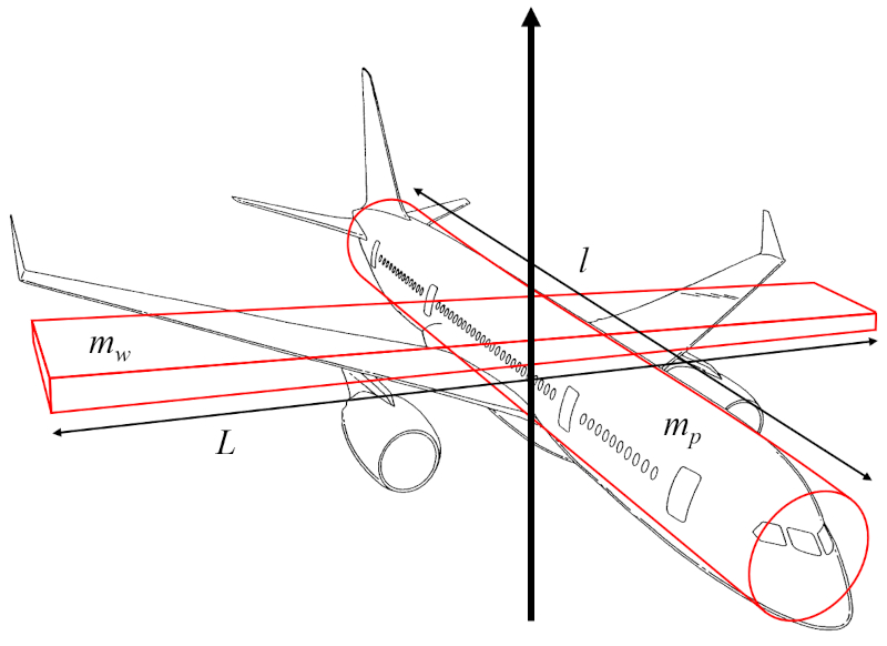
If, for the estimation of the vertical axis moment of inertia (I_r), it is assumed that the radius of the fuselage cylinder is much smaller than the distance along the wing (l) and the wing width (w) is much smaller than the wing span (L), the moment of inertia of the cylinder primarily depends on the aircraft body mass (m_p) and the distance along the wing (l), while the moment of inertia of the parallelepiped depends on the wing mass (m_w) and the wing span (L).
Therefore, the vertical axis moment of inertia (I_r) is calculated using the aircraft body mass (m_p), the wing mass (m_w), the wing span (L), and the distance along the wing (l) as follows:
ID:(15993, 0)
Force that generates the yaw
Equation
ID:(15165, 0)
Yaw torque
Equation
ID:(15168, 0)
Lift force
Equation
To generate higher pressure below than above the wing and generate lift, Bernoulli's principle is employed, correcting for the lack of energy density conservation using ($$). The pressure over the wing, the lift force (F_L), can be estimated using the density (\rho), the surface that generates lift (S_w), the coefficient of lift (C_L), and the speed with respect to the medium (v) through the following formula:
The lift force (F_L), along with the wing span (L), the density (\rho), the wing top speed factor (c_t), the wing bottom speed factor (c_b), the upper wing length (l_t), the bottom wing length (l_b), and the speed with respect to the medium (v), is found in
| F_L = \rho L ( c_b l_b - c_t l_t ) v ^2 |
If we consider the surface that generates lift (S_w), given by the wing span (L), the upper wing length (l_t), and the bottom wing length (l_b),
| S_w = \displaystyle\frac{1}{2} L ( l_t + l_b ) |
and for the coefficient of lift (C_L), defined as
| C_L = 4\displaystyle\frac{ c_t l_t - c_b l_b }{ l_t + l_b } |
we obtain
| F_L =\displaystyle\frac{1}{2} \rho S_w C_L v ^2 |
ID:(4417, 0)
Lift constant
Equation
From measurements, it is concluded that the lift coefficient C_L is proportional to the angle of attack \alpha:
After a certain angle, the curve decreases until it reaches zero. This is because beyond that critical angle, the vortices fully cover the upper surface of the wing, leading to a loss of lift. This phenomenon is known as \"stall\".
ID:(4441, 0)
Moment of inertia for yaw
Equation
The vertical axis moment of inertia (I_r) is calculated from the wing mass (m_w), the wing span (L) and the distance along the wing (l), as follows:
ID:(15988, 0)
Wing mass
Equation
The wing mass (m_w) is calculated from the aircraft body density (\rho_a), the surface that generates lift (S_w), and the wing height (d), as follows:
ID:(15984, 0)
Aircraft body mass
Equation
The aircraft body mass (m_p) is calculated from the aircraft body density (\rho_a), the total object profile (S_p), and the distance along the wing (l), as follows:
ID:(15985, 0)
Arm of the rudder force
Equation
The center of mass and rudder distance (d_r) is defined as half of the distance along the wing (l), expressed as follows:
ID:(15996, 0)
Thickness to span ratio
Equation
The thickness to span ratio (\gamma_d) is defined as the ratio of the wing height (d) to the wing span (L), represented as follows:
ID:(15976, 0)