
Pitch control
Storyboard 
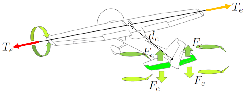
Pitch control is the mechanism that allows the aircraft's nose to be raised or lowered, which is essential for ascending or descending movement. This control is achieved by generating lift through the elevators located on the smaller wings near the tail of the aircraft. This lift creates a torque, responsible for causing the aircraft to rotate around an imaginary axis, parallel to the main wings, known as the pitch axis.
ID:(2113, 0)
Pitch control
Concept
To pitch the aircraft's nose up or down, the elevators are used. Both elevators are employed in a symmetrical manner to generate a the force in the elevators (F_e) symmetric effect. Placing them at the tail of the aircraft achieves ($$) greater effectiveness by locating them near the center of mass. This provides sufficient control to raise or lower the aircraft's nose.
In older aircraft, control of the rear ailerons is achieved through a control stick, where pushing forward causes the aircraft's nose to descend, and pulling backward raises the nose. In Airbus family aircraft, this control is accomplished using a joystick.
In the case of birds, a similar solution exists, although in this case, the tail is not interrupted by a rudder.
ID:(15161, 0)

Wing mass
Description
The wing mass (m_w) can be approximated as the volume of a rectangular parallelepiped multiplied by the density of the aircraft:
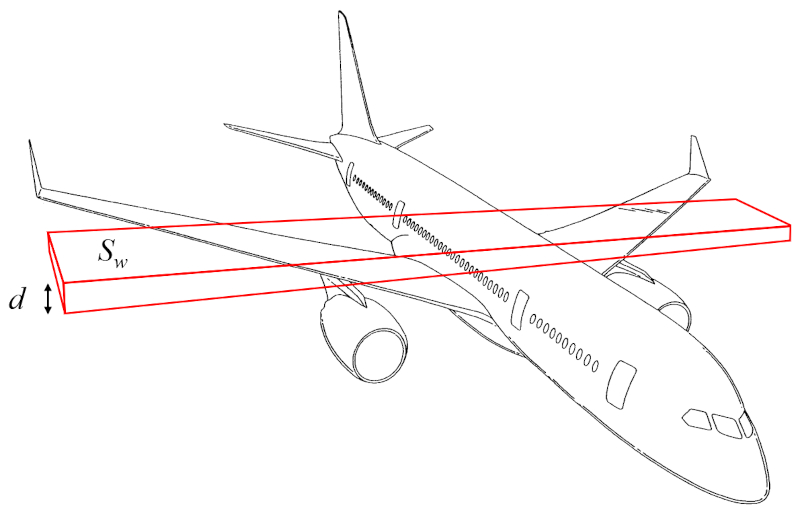
The volume can thus be calculated from the surface that generates lift (S_w) and the wing height (d).
Therefore, the wing mass (m_w) is determined using the aircraft body density (\rho_a), the surface that generates lift (S_w), and the wing height (d), as follows:
| m_w = \rho_a S_w d |
ID:(15989, 0)
Moment of inertia for pitching
Description
The wing axis moment of inertia (I_e) can be approximated as the moment of inertia of a cylinder representing the body of the aircraft, rotating around an axis perpendicular to the cylinder's axis, which is parallel to the wings:
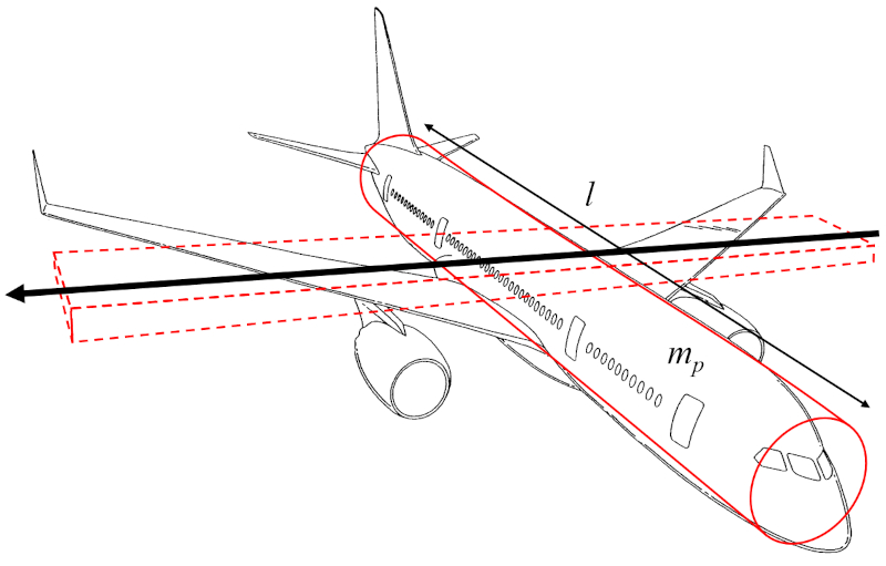
Since the wing width (w) is much smaller than the distance along the wing (l), the term involving w^2 can be neglected, focusing only on the aircraft body mass (m_p) and the term with the distance along the wing (l) squared.
Therefore, the wing axis moment of inertia (I_e) is calculated using the aircraft body mass (m_p) and the distance along the wing (l) as follows:
ID:(15991, 0)
Model
Top
Parameters
Variables
Calculations
Calculations
Calculations
Equations
C_L = c \alpha
C_L = c * alpha
d_e = \displaystyle\frac{ l }{2}
d_e = l /2
F_L =\displaystyle\frac{1}{2} \rho S_e C_L v ^2
F_L = rho * S_w * C_L * v ^2/2
I_e = \displaystyle\frac{1}{12} m_p l ^2
I_e = m_p * l ^2/12
m_p = \rho_a S_p l
m_p = rha_a * S_p * l
T_e = d_e F_L
T_e = d_e * F_e
T_e = I_e \alpha_e
T_e = I_e * alpha_e
ID:(15172, 0)
Force generated by pitching
Equation
ID:(15163, 0)
Pitch torque
Equation
ID:(15166, 0)
Lift force
Equation
To generate higher pressure below than above the wing and generate lift, Bernoulli's principle is employed, correcting for the lack of energy density conservation using ($$). The pressure over the wing, the lift force (F_L), can be estimated using the density (\rho), the surface that generates lift (S_w), the coefficient of lift (C_L), and the speed with respect to the medium (v) through the following formula:
The lift force (F_L), along with the wing span (L), the density (\rho), the wing top speed factor (c_t), the wing bottom speed factor (c_b), the upper wing length (l_t), the bottom wing length (l_b), and the speed with respect to the medium (v), is found in
| F_L = \rho L ( c_b l_b - c_t l_t ) v ^2 |
If we consider the surface that generates lift (S_w), given by the wing span (L), the upper wing length (l_t), and the bottom wing length (l_b),
| S_w = \displaystyle\frac{1}{2} L ( l_t + l_b ) |
and for the coefficient of lift (C_L), defined as
| C_L = 4\displaystyle\frac{ c_t l_t - c_b l_b }{ l_t + l_b } |
we obtain
| F_L =\displaystyle\frac{1}{2} \rho S_w C_L v ^2 |
ID:(4417, 0)
Lift constant
Equation
From measurements, it is concluded that the lift coefficient C_L is proportional to the angle of attack \alpha:
After a certain angle, the curve decreases until it reaches zero. This is because beyond that critical angle, the vortices fully cover the upper surface of the wing, leading to a loss of lift. This phenomenon is known as \"stall\".
ID:(4441, 0)
Moment of inertia for pitching
Equation
The wing mass (m_w) is calculated from the aircraft body mass (m_p) and the distance along the wing (l), as follows:
ID:(15987, 0)
Aircraft body mass
Equation
The aircraft body mass (m_p) is calculated from the aircraft body density (\rho_a), the total object profile (S_p), and the distance along the wing (l), as follows:
ID:(15985, 0)
Pitch force arm
Equation
The distance center of mass and elevators (d_e) is defined as half of the distance along the wing (l), expressed as follows:
ID:(15994, 0)