Water Flow
Storyboard 
In saturated soil, there can be situations where pressure variations occur. These variations, in turn, generate flow that, in this case, should occur within the soil pores. Since these pores are on the order of microns or tens of microns, the flow tends to be laminar due to the low Reynolds numbers.
ID:(369, 0)
Flux density solution from a channel
Concept 
The solution obtained for the height and the parameters the flow at a reference point (j_{s0}) and the reference height of the water column (h_0) shows us that the flux density (j_s) is equal to:
| \displaystyle\frac{ j_s }{ j_{s0} } = \displaystyle\frac{1}{\sqrt{1 - \displaystyle\frac{ 2 x }{ s_0 }}} |
We can graphically represent the flux density (j_s) in terms of the additional factors j_s/j_{s0} and x/x_0 as follows:

the flux density (j_s) continues to increase as we approach the channel, as the height of the water column on the ground (h) decreases. This increase is necessary to maintain the flow velocity in the flux density (j_s) or, alternatively, to increase it.
ID:(7827, 0)
Laminar flow through a tube
Concept 
When a tube filled with liquid with a viscosity of viscosity (\eta) is exposed to the pressure in the initial position (p_i) at the position at the beginning of the tube (L_i) and the pressure in end position (e) (p_e) at the position at the end of the tube (L_e), it generates a pressure difference (\Delta p_s) along the tube length (\Delta L), resulting in the profile of the speed on a cylinder radio (v):
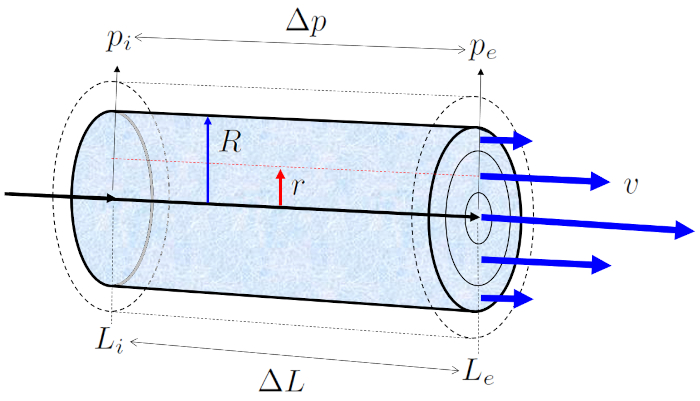
In flows with low values of the number of Reynold (Re), where viscosity is more significant than the inertia of the liquid, the flow develops in a laminar manner, meaning without the presence of turbulence.
ID:(2218, 0)
Laminars in the stream
Concept 
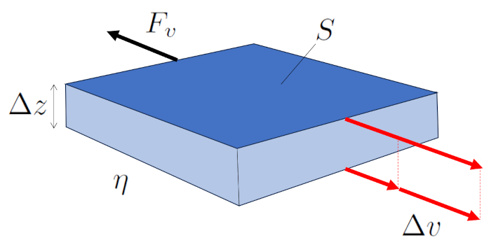
In laminar flow, adjacent layers move, and there exists a force generated by viscosity between them. The faster layer drags its slower neighbor, while the slower one restricts the advancement of the faster one.
Therefore, the force the viscose force (F_v) generated by ($$) over the other is a function of ($$), ($$), and ($$), as depicted in the following equation:
| F_v =- S \eta \displaystyle\frac{ \Delta v }{ \Delta z } |
illustrated in the following diagram:
ID:(7053, 0)
Flow through a cylinder
Concept 
Laminar flow around a cylinder can be represented as multiple cylindrical layers sliding under the influence of adjacent layers. In this case, the viscose force (F_v) with the tube length (\Delta L), the viscosity (\eta), and the variables the cylinder radial position (r) and the speed on a cylinder radio (v) is expressed as:
| F_v =-2 \pi r \Delta L \eta \displaystyle\frac{ dv }{ dr } |
The layer at the boundary at ($$) remains stationary due to the boundary effect and, through the viscosity (\eta), slows down the adjacent layer which does have velocity.
The center is the part moving at the maximum flow rate (v_{max}), dragging the surrounding layer. In turn, this layer drags the next one, and so on until reaching the layer in contact with the cylinder wall, which is stationary.
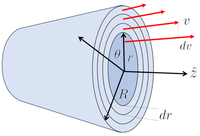
Thus, the system transfers energy from the center to the wall, generating a velocity profile represented by:
| v = v_{max} \left(1-\displaystyle\frac{ r ^2}{ R ^2}\right) |
with:
| v_{max} =-\displaystyle\frac{ R ^2}{4 \eta }\displaystyle\frac{ \Delta p }{ \Delta L } |
ID:(7057, 0)
Flow after Hagen-Poiseuille equation
Concept 
The profile of the speed on a cylinder radio (v) in the radius of position in a tube (r) allows us to calculate the volume flow (J_V) in a tube by integrating over the entire surface, which leads us to the well-known Hagen-Poiseuille law.
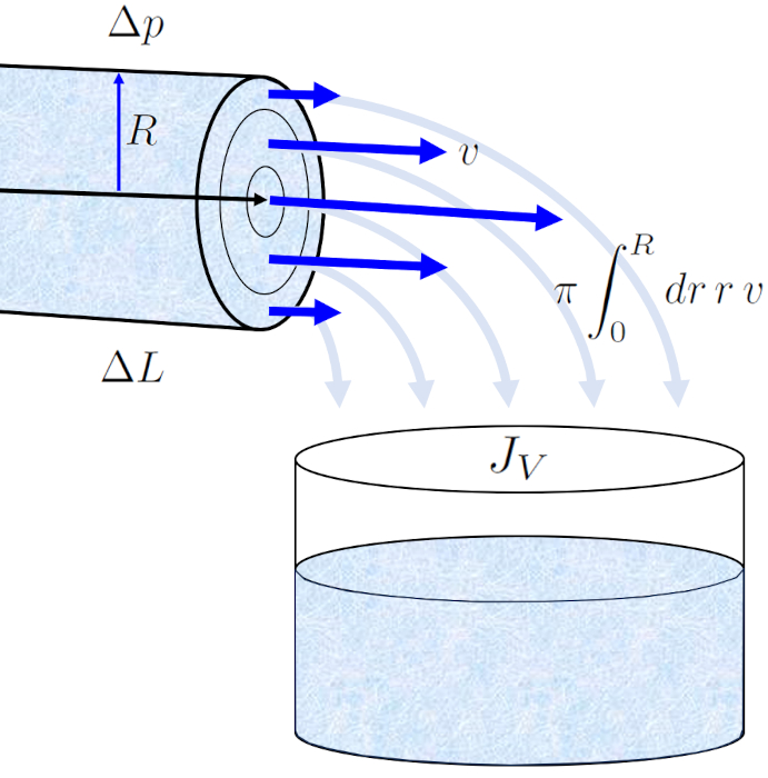
The result is an equation that depends on tube radius (R) raised to the fourth power. However, it is crucial to note that this flow profile only holds true in the case of laminar flow.
Thus, from the viscosity (\eta), it follows that the volume flow (J_V) before ($$) and ($$), the expression:
| J_V =-\displaystyle\frac{ \pi R ^4}{8 \eta }\displaystyle\frac{ \Delta p }{ \Delta L } |
The original papers that gave rise to this law with a combined name were:
![]() "Ueber die Gesetze, welche des der Strom des Wassers in röhrenförmigen Gefässen bestimmen" (On the laws governing the flow of water in cylindrical vessels), Gotthilf Hagen, Annalen der Physik und Chemie 46:423442 (1839).
"Ueber die Gesetze, welche des der Strom des Wassers in röhrenförmigen Gefässen bestimmen" (On the laws governing the flow of water in cylindrical vessels), Gotthilf Hagen, Annalen der Physik und Chemie 46:423442 (1839).
![]() "Recherches expérimentales sur le mouvement des liquides dans les tubes de très-petits diamètres" (Experimental research on the movement of liquids in tubes of very small diameters), Jean-Louis-Marie Poiseuille, Comptes Rendus de l'Académie des Sciences 9:433544 (1840).
"Recherches expérimentales sur le mouvement des liquides dans les tubes de très-petits diamètres" (Experimental research on the movement of liquids in tubes of very small diameters), Jean-Louis-Marie Poiseuille, Comptes Rendus de l'Académie des Sciences 9:433544 (1840).
ID:(2216, 0)
Volume flow
Concept 
During a time elapsed (\Delta t), the fluid with a mean Speed of Fluid (v) moves a tube element (\Delta s). If the section (S) represents the amount of fluid crossing that section in the time elapsed (\Delta t), it is calculated as:
\Delta V = S \Delta s = Sv \Delta t
This equation states that the volume of fluid flowing through section the section (S) during a time elapsed (\Delta t) is equal to the product of the cross-sectional area and the distance the fluid travels during that time.
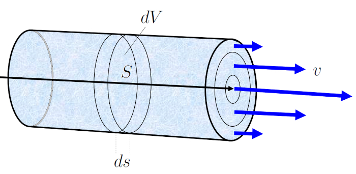
This facilitates the calculation of the volume element (\Delta V), which is the volume of fluid flowing through the channel in a specific period of the time elapsed (\Delta t), corresponding to the volume flow (J_V).
| J_V =\displaystyle\frac{ \Delta V }{ \Delta t } |
ID:(2212, 0)
Model
Top 
Parameters
Variables
Calculations
Calculations
Calculations
Equations
\Delta L = L_e - L_i
DL = L_e - L_i
\Delta p = p_e - p_i
Dp = p_e - p_i
\Delta p = R_h J_V
Dp = R_h * J_V
F_v =- S \eta \displaystyle\frac{ \Delta v }{ \Delta z }
F_v =- S * eta * Dv / Dz
F_v =-2 \pi r \Delta L \eta \displaystyle\frac{ dv }{ dr }
F_v =-2* pi * r * DL * eta *( dv / dr )
G_h =\displaystyle\frac{ \pi R ^4}{8 \eta | \Delta L | }
G_h = pi * R ^4/(8* eta * abs( DL ))
j_s = \displaystyle\frac{ J_V }{ S }
j_s = J_V / S
J_V =\displaystyle\frac{ dV }{ dt }
J_V = @DIFF( V , t , 1 )
J_V = G_h \Delta p
J_V = G_h * Dp
J_V =-\displaystyle\frac{ \pi R ^4}{8 \eta }\displaystyle\frac{ \Delta p }{ \Delta L }
J_V =- pi * R ^4* Dp /(8* eta * DL )
k = \displaystyle\frac{ R ^2}{8}
k = R ^2/8
Re =\displaystyle\frac{ \rho R v }{ \eta }
Re = rho * R * v / eta
R_h = \displaystyle\frac{1}{ G_h }
R_h = 1/ G_h
R_h =\displaystyle\frac{8 \eta | \Delta L | }{ \pi R ^4}
R_h =8* eta * abs( DL )/( pi * R ^4)
S = \pi r ^2
S = pi * r ^2
v = v_{max} \left(1-\displaystyle\frac{ r ^2}{ R ^2}\right)
v = v_max *(1- ( r / R )^2)
v_{max} =-\displaystyle\frac{ R ^2}{4 \eta }\displaystyle\frac{ \Delta p }{ \Delta L }
v_max = - R ^2* Dp /(4* DL * eta )
ID:(15221, 0)
Reynold Number
Equation 
The key criterion for determining whether a medium is laminar or turbulent is the Reynolds number, which compares the energy associated with inertia to that associated with viscosity. The former depends on the density (\rho), the mean Speed of Fluid (v), and the typical Dimension of the System (R), while the latter depends on the viscosity (\eta), defining it as:
ID:(3177, 0)
Pressure difference
Equation 
When the pressure in the initial position (p_i) and the pressure in end position (e) (p_e) are connected, a the pressure difference (\Delta p_s) is created, which is calculated using the following formula:
the pressure difference (\Delta p_s) represents the pressure difference that will cause the liquid to flow from the taller column to the shorter one.
ID:(14459, 0)
Change in length
Equation 
To describe the flow, a coordinate system is defined in which the liquid flows from the position at the beginning of the tube (L_i) to the position at the end of the tube (L_e), indicating that the pressure at the pressure in the initial position (p_i) is greater than at the pressure in end position (e) (p_e). This movement depends on the tube length (\Delta L), which is calculated as follows:
ID:(3802, 0)
Viscose force
Equation 
The viscose force (F_v) can be calculated from the parallel surfaces (S), the viscosity (\eta), the speed difference between surfaces (\Delta v), and the distance between surfaces (\Delta z) using the following method:
ID:(3622, 0)
Viscose force, cylinder case
Equation 
In the case of a cylinder, the surface is defined by tube length (\Delta L), and by the perimeter of each of the internal cylinders, which is calculated by multiplying 2\pi by the radius of position in a tube (r). With this, the cylinder resistance force (F_v) is calculated using the viscosity (\eta) and the variation of speed between two radii (dv) for the width of the cylinder the radius variation in a tube (dr), resulting in:
As the viscous force is
| F_v =- S \eta \displaystyle\frac{ \Delta v }{ \Delta z } |
and the surface area of the cylinder is
S=2\pi R L
where R is the radius and L is the length of the channel, the viscous force can be expressed as
| F_v =-2 \pi r \Delta L \eta \displaystyle\frac{ dv }{ dr } |
where \eta represents the viscosity and dv/dr is the velocity gradient between the wall and the flow.
ID:(3623, 0)
Speed profile of flow in a cylinder
Equation 
When solving the flow equation with the boundary condition, we obtain the speed on a cylinder radio (v) as a function of the curvature radio (r), represented by a parabola centered at the maximum flow rate (v_{max}) and equal to zero at the tube radius (R):
When a the pressure difference (\Delta p_s) acts on a section with an area of \pi R^2, with the tube radius (R) as the curvature radio (r), it generates a force represented by:
\pi r^2 \Delta p
This force drives the liquid against viscous resistance, given by:
| F_v =-2 \pi r \Delta L \eta \displaystyle\frac{ dv }{ dr } |
By equating these two forces, we obtain:
\pi r^2 \Delta p = \eta 2\pi r \Delta L \displaystyle\frac{dv}{dr}
Which leads to the equation:
\displaystyle\frac{dv}{dr} = \displaystyle\frac{1}{2\eta}\displaystyle\frac{\Delta p}{\Delta L} r
If we integrate this equation from a position defined by the curvature radio (r) to the edge where the tube radius (R) (taking into account that the velocity at the edge is zero), we can obtain the speed on a cylinder radio (v) as a function of the curvature radio (r):
| v = v_{max} \left(1-\displaystyle\frac{ r ^2}{ R ^2}\right) |
Where:
| v_{max} =-\displaystyle\frac{ R ^2}{4 \eta }\displaystyle\frac{ \Delta p }{ \Delta L } |
is the maximum flow rate (v_{max}) at the center of the flow.
.
ID:(3627, 0)
Maximal speed of flow in a cylinder
Equation 
The value of the maximum flow rate (v_{max}) at the center of a cylinder depends on the viscosity (\eta), the tube radius (R), and the gradient created by the pressure difference (\Delta p_s) and the tube length (\Delta L), as represented by:
The negative sign indicates that the flow always occurs in the direction opposite to the gradient, meaning from the area of higher pressure to the area of lower pressure.
ID:(3628, 0)
Instant Volume Flow
Equation 
The volume flow (J_V) corresponds to the quantity volume (V) that flows through the channel during a time (t). Therefore, we have:
The definition of the volume flow (J_V) is the volume element (\Delta V) over the time elapsed (\Delta t):
| J_V =\displaystyle\frac{ \Delta V }{ \Delta t } |
which, in the limit of an infinitesimal time interval, corresponds to the derivative of the volume (V) with respect to the time (t):
| J_V =\displaystyle\frac{ dV }{ dt } |
ID:(12713, 0)
Hagen Poiseuille Equation
Equation 
The volume flow (J_V) can be calculated with the Hagen-Poiseuille law that with the parameters the viscosity (\eta), the pressure difference (\Delta p), the tube radius (R) and the tube length (\Delta L) is:
If we consider the profile of speed on a cylinder radio (v) for a fluid in a cylindrical channel, where the speed on a cylinder radio (v) varies with respect to radius of position in a tube (r) according to the following expression:
| v = v_{max} \left(1-\displaystyle\frac{ r ^2}{ R ^2}\right) |
involving the tube radius (R) and the maximum flow rate (v_{max}). We can calculate the maximum flow rate (v_{max}) using the viscosity (\eta), the pressure difference (\Delta p), and the tube length (\Delta L) as follows:
| v_{max} =-\displaystyle\frac{ R ^2}{4 \eta }\displaystyle\frac{ \Delta p }{ \Delta L } |
If we integrate the velocity across the cross-section of the channel, we obtain the volume flow (J_V), defined as the integral of \pi r v(r) with respect to radius of position in a tube (r) from 0 to tube radius (R). This integral can be simplified as follows:
J_V=-\displaystyle\int_0^Rdr \pi r v(r)=-\displaystyle\frac{R^2}{4\eta}\displaystyle\frac{\Delta p}{\Delta L}\displaystyle\int_0^Rdr \pi r \left(1-\displaystyle\frac{r^2}{R^2}\right)
The integration yields the resulting Hagen-Poiseuille law:
| J_V =-\displaystyle\frac{ \pi R ^4}{8 \eta }\displaystyle\frac{ \Delta p }{ \Delta L } |
ID:(3178, 0)
Hydraulic Conductance of a Pipe
Equation 
With the tube radius (R), the viscosity (\eta) and the tube length (\Delta L) we have that a hydraulic conductance (G_h) is:
ID:(15102, 0)
Darcy's law and hydraulic conductance
Equation 
With the introduction of the hydraulic conductance (G_h), we can rewrite the Hagen-Poiseuille equation with the pressure difference (\Delta p) and the volume flow (J_V) using the following equation:
If we examine the Hagen-Poiseuille law, which allows us to calculate the volume flow (J_V) from the tube radius (R), the viscosity (\eta), the tube length (\Delta L), and the pressure difference (\Delta p):
| J_V =-\displaystyle\frac{ \pi R ^4}{8 \eta }\displaystyle\frac{ \Delta p }{ \Delta L } |
we can introduce the hydraulic conductance (G_h), defined in terms of the tube length (\Delta L), the tube radius (R), and the viscosity (\eta), as follows:
| G_h =\displaystyle\frac{ \pi R ^4}{8 \eta | \Delta L | } |
to arrive at:
| J_V = G_h \Delta p |
ID:(14471, 0)
Hydraulic conductance
Equation 
In the context of electrical resistance, there exists its inverse, known as electrical conductance. Similarly, what would be the hydraulic conductance (G_h) can be defined in terms of the hydraulic resistance (R_h) through the expression:
ID:(15092, 0)
Hydraulic resistance of a tube
Equation 
Since the hydraulic resistance (R_h) is equal to the inverse of the hydraulic conductance (G_h), it can be calculated from the expression of the latter. In this way, we can identify parameters related to geometry (the tube length (\Delta L) and the tube radius (R)) and the type of liquid (the viscosity (\eta)), which can be collectively referred to as a hydraulic resistance (R_h):
Since the hydraulic resistance (R_h) is equal to the hydraulic conductance (G_h) as per the following equation:
| R_h = \displaystyle\frac{1}{ G_h } |
and since the hydraulic conductance (G_h) is expressed in terms of the viscosity (\eta), the tube radius (R), and the tube length (\Delta L) as follows:
| G_h =\displaystyle\frac{ \pi R ^4}{8 \eta | \Delta L | } |
we can conclude that:
| R_h =\displaystyle\frac{8 \eta | \Delta L | }{ \pi R ^4} |
ID:(3629, 0)
Darcy's law and hydraulic resistance
Equation 
Darcy rewrites the Hagen Poiseuille equation so that the pressure difference (\Delta p) is equal to the hydraulic resistance (R_h) times the volume flow (J_V):
The volume flow (J_V) can be calculated from the hydraulic conductance (G_h) and the pressure difference (\Delta p) using the following equation:
| J_V = G_h \Delta p |
Furthermore, using the relationship for the hydraulic resistance (R_h):
| R_h = \displaystyle\frac{1}{ G_h } |
results in:
| \Delta p = R_h J_V |
ID:(3179, 0)
Surface of a disk
Equation 
The surface of a disk (S) of ($$) is calculated as follows:
ID:(3804, 0)
Volume Flow and its Speed
Equation 
A flux density (j_s) can be expressed in terms of the volume flow (J_V) using the section or Area (S) through the following formula:
Flow is defined as the volume the volume element (\Delta V) divided by time the time elapsed (\Delta t), which is expressed in the following equation:
| J_V =\displaystyle\frac{ \Delta V }{ \Delta t } |
and the volume equals the cross-sectional area the section Tube (S) multiplied by the distance traveled the tube element (\Delta s):
| \Delta V = S \Delta s |
Since the distance traveled the tube element (\Delta s) per unit time the time elapsed (\Delta t) corresponds to the velocity, it is represented by:
| j_s =\displaystyle\frac{ \Delta s }{ \Delta t } |
Thus, the flow is a flux density (j_s), which is calculated using:
| j_s = \displaystyle\frac{ J_V }{ S } |
ID:(4349, 0)
Hydraulic permeability
Equation 
The remaining factor is called the hydrodynamic permeability (k) and can be calculated using the tube radius (R) with the following formula:
If we examine the hydraulic conductance (G_h), we can notice that the numerator contains the cross-sectional area of the tube, represented as \pi R^2. Here, the tube radius (R) corresponds to a property of the liquid, the viscosity (\eta) is related to the viscosity of the fluid, and the tube length (\Delta L) refers to the generated pressure gradient.
| G_h =\displaystyle\frac{ \pi R ^4}{8 \eta | \Delta L | } |
Thus, the factor specific to the geometry of the pores can be defined as the hydrodynamic permeability (k) using the following formula:
| k = \displaystyle\frac{ R ^2}{8} |
ID:(108, 0)
