Bombas de rotor y centrifugas
Image 
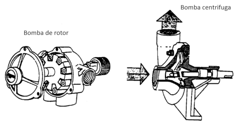
Los dos principales mecanismos sobre los que se basan las bombas son de rotor (desplazan liquido) y las centrifugas que aceleran el liquido radialmente para generar el movimiento.

ID:(12894, 0)
Comparación entre bombas
Image 
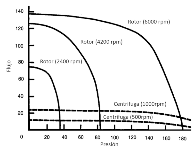
Las bombas centrifugas logran un menor flujo pero parejo sobre un mayor rango de diferencia de presiones:

ID:(12896, 0)
Bernoulli equation, variations
Equation 
The variación de la Presión ($\Delta p$) can be calculated from the average speed ($\bar{v}$) and the speed difference between surfaces ($\Delta v$) with the density ($\rho$) using
In the case where there is no hystrostatic pressure, Bernoulli's law for the density ($\rho$), the pressure in column 1 ($p_1$), the pressure in column 2 ($p_2$), the mean Speed of Fluid in Point 1 ($v_1$) and the mean Speed of Fluid in Point 2 ($v_2$)
| $\displaystyle\frac{1}{2} \rho v_1 ^2 + p_1 =\displaystyle\frac{1}{2} \rho v_2 ^2 + p_2 $ |
can be rewritten with the variación de la Presión ($\Delta p$)
| $ \Delta p = p_2 - p_1 $ |
and keeping in mind that
$v_2^2 - v_1^2 = \displaystyle\frac{1}{2}(v_2-v_1)(v_1+v_2)$
with
| $ \bar{v} = \displaystyle\frac{ v_1 + v_2 }{2}$ |
and
| $ \Delta v = v_2 - v_1 $ |
you have to
| $ \Delta p = - \rho \bar{v} \Delta v $ |
which allows us to see the effect of the average speed of a body and the difference between its surfaces, as observed in an airplane or bird wing.
ID:(4835, 0)
Darcy's law and hydraulic resistance
Equation 
Darcy rewrites the Hagen Poiseuille equation so that the pressure difference ($\Delta p$) is equal to the hydraulic resistance ($R_h$) times the volume flow ($J_V$):
The volume flow ($J_V$) can be calculated from the hydraulic conductance ($G_h$) and the pressure difference ($\Delta p$) using the following equation:
| $ J_V = G_h \Delta p $ |
Furthermore, using the relationship for the hydraulic resistance ($R_h$):
| $ R_h = \displaystyle\frac{1}{ G_h }$ |
results in:
| $ \Delta p = R_h J_V $ |
ID:(3179, 0)
Hydraulic resistance of a tube
Equation 
Since the hydraulic resistance ($R_h$) is equal to the inverse of the hydraulic conductance ($G_h$), it can be calculated from the expression of the latter. In this way, we can identify parameters related to geometry (the tube length ($\Delta L$) and the tube radius ($R$)) and the type of liquid (the viscosity ($\eta$)), which can be collectively referred to as a hydraulic resistance ($R_h$):
Since the hydraulic resistance ($R_h$) is equal to the hydraulic conductance ($G_h$) as per the following equation:
| $ R_h = \displaystyle\frac{1}{ G_h }$ |
and since the hydraulic conductance ($G_h$) is expressed in terms of the viscosity ($\eta$), the tube radius ($R$), and the tube length ($\Delta L$) as follows:
| $ G_h =\displaystyle\frac{ \pi R ^4}{8 \eta | \Delta L | }$ |
we can conclude that:
| $ R_h =\displaystyle\frac{8 \eta | \Delta L | }{ \pi R ^4}$ |
ID:(3629, 0)
Parallel hydraulic conductivity
Concept 
If we have three hydraulic resistances $R_{h1}$, $R_{h2}$, and $R_{h3}$, the series sum of the resistances will be:
ID:(3631, 0)


