Laminar flow, ink
Description 
One effective way to demonstrate laminar flow is by injecting ink into a flow using a thin needle that does not disturb it. This technique allows for a clear visualization of fluid layers sliding without mixing with each other. The ink disperses in the fluid in an orderly manner, creating distinct lines that reveal the direction and pattern of laminar flow. This method is widely used in experiments and demonstrations to visually illustrate the characteristics and properties of laminar flow in a visually impactful way.

ID:(7059, 0)
Laminar flow images
Description 
The observation in the laboratory demonstrates how ink creates a line (in this case, red). When the experiment is repeated at different positions, a pattern of layers becomes evident, indicating laminar flow.
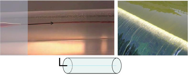
Liquids flowing in a laminar manner exhibit a smooth channel without the presence of eddies or abrupt lateral movements.
ID:(7060, 0)
Turbulent flow, ink
Description 
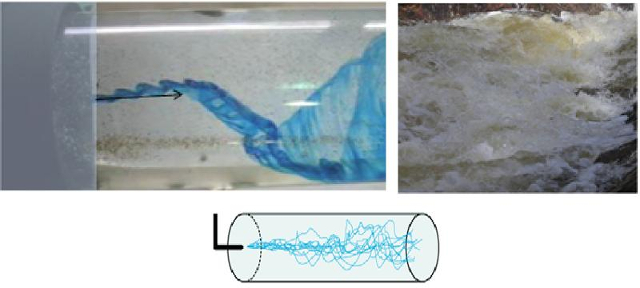
One way to visualize turbulent flow is by injecting ink into a flow using a thin needle that doesn't disturb the flow.

The resulting behavior shows abrupt deviation and a degree of diffusion caused by the turbulence in the flow.
ID:(7064, 0)
Turbulent flow image
Description 
In the laboratory, blue ink is injected, which significantly deviates from a linear flow, revealing the presence of vortices and a degree of diffusion due to smaller amplitude disturbances.
ID:(7067, 0)
Turbulence evolution according to Reynold number
Concept 
The behavior of the flow around a sphere undergoes dramatic changes depending on the number of Reynold (Re), which is calculated as a function of the typical Dimension of the System (R), corresponding in this case to the radius of the sphere. Additionally, the number of Reynold (Re) is a function of the mean Speed of Fluid (v), the density (\rho), and the viscosity (\eta) as follows:
| Re =\displaystyle\frac{ \rho R v }{ \eta } |
the number of Reynold (Re) expresses the ratio between the systems inertia and viscosity. When viscosity dominates, the flow exhibits laminar behavior, whereas when inertia dominates, the flow becomes turbulent. In the former case, the medium has time to adjust, while in the latter, the flow does not have enough time, resulting in the formation of vortices or even chaotic behavior.
The following diagram summarizes the different flow behaviors:
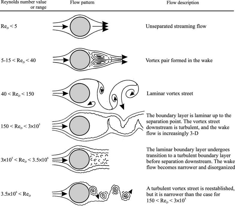
Flow type scheme according to Reynold number (book Introduction to Transport Phenomena Modeling, Gianpaolo Ruocco - https://link.springer.com/chapter/10.1007/978-3-319-66822-2_3)
ID:(1890, 0)
Coefficient of hydraulic resistance
Concept 
The coefficient of resistance (C_W) varies as a function of the number of Reynold (Re) according to:
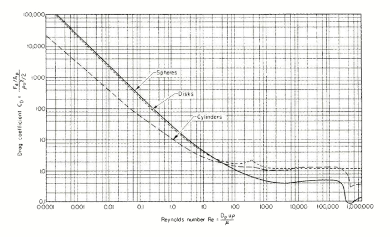
which can be estimated using the empirical equation:
| C_W = \displaystyle\frac{24}{ Re }(1 + 0.15 Re ^{0.687}) |
Thus, the resistance force (F_W) can be calculated using the density (\rho), the total object profile (S_p), and the speed with respect to the medium (v) by:
| F_W =\displaystyle\frac{1}{2} \rho S_p C_W v ^2 |
ID:(7065, 0)
Flow simulation around an obstacle
Description 
To study flow at the boundary between laminar and turbulent regimes, you can use the simulator developed by Dan Schroeder from the Physics Department at Weber State University:
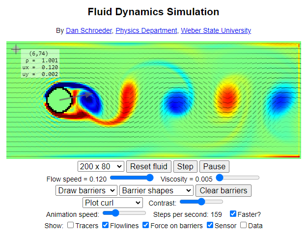
Access the simulator directly through the following link: Fluid Dynamics Simulation.
ID:(15901, 0)
Model
Top 
Parameters
Variables
Calculations
Calculations
Calculations
Equations
C_W = \displaystyle\frac{24}{ Re }(1 + 0.15 Re ^{0.687})
C_W =24*(1+ Re ^0.687)/ Re
F_L =\displaystyle\frac{1}{2} \rho S_w C_L v ^2
F_L = rho * S_w * C_L * v ^2/2
F_W =\displaystyle\frac{1}{2} \rho S_p C_W v ^2
F_W = rho * S_p * C_W * v ^2/2
Re =\displaystyle\frac{ \rho R v }{ \eta }
Re = rho * R * v / eta
ID:(15733, 0)
Reynold Number
Equation 
The key criterion for determining whether a medium is laminar or turbulent is the Reynolds number, which compares the energy associated with inertia to that associated with viscosity. The former depends on the density (\rho), the mean Speed of Fluid (v), and the typical Dimension of the System (R), while the latter depends on the viscosity (\eta), defining it as:
ID:(3177, 0)
Lift force
Equation 
To generate higher pressure below than above the wing and generate lift, Bernoulli's principle is employed, correcting for the lack of energy density conservation using ($$). The pressure over the wing, the lift force (F_L), can be estimated using the density (\rho), the surface that generates lift (S_w), the coefficient of lift (C_L), and the speed with respect to the medium (v) through the following formula:
The lift force (F_L), along with the wing span (L), the density (\rho), the wing top speed factor (c_t), the wing bottom speed factor (c_b), the upper wing length (l_t), the bottom wing length (l_b), and the speed with respect to the medium (v), is found in
| F_L = \rho L ( c_b l_b - c_t l_t ) v ^2 |
If we consider the surface that generates lift (S_w), given by the wing span (L), the upper wing length (l_t), and the bottom wing length (l_b),
| S_w = \displaystyle\frac{1}{2} L ( l_t + l_b ) |
and for the coefficient of lift (C_L), defined as
| C_L = 4\displaystyle\frac{ c_t l_t - c_b l_b }{ l_t + l_b } |
we obtain
| F_L =\displaystyle\frac{1}{2} \rho S_w C_L v ^2 |
ID:(4417, 0)
Resistance force
Equation 
The resistance force (F_W) kann mit the density (\rho), the coefficient of resistance (C_W), the total object profile (S_p) und the speed with respect to the medium (v) entsprechend berechnet werden folgende Formel:
Similarly to how the equation for the lift force (F_L) was derived using the density (\rho), the coefficient of lift (C_L), the surface that generates lift (S_w), and the speed with respect to the medium (v)
| F_L =\displaystyle\frac{1}{2} \rho S_w C_L v ^2 |
in this analogy, what corresponds to the surface that generates lift (S_w) will be equivalent to the total object profile (S_p) and the coefficient of lift (C_L) to the coefficient of resistance (C_W), thus the resistance force (F_W) is calculated:
| F_W =\displaystyle\frac{1}{2} \rho S_p C_W v ^2 |
The drag coefficient is measured and, in turbulent flows over aerodynamic bodies, values are generally found around 0.4.
ID:(4418, 0)
Drag coefficient of a sphere
Equation 
Empirically, the coefficient of resistance (C_W) can be modeled as a function of the number of Reynold (Re) as follows:
ID:(15900, 0)
