Buoyancy stability
Storyboard 
The force generated by buoyancy acts at the center of the displaced volume, which is typically lower than the center of mass of the object in the water. This pair of forces results in torques that can either stabilize or destabilize the object. In the latter case, it may even end up overturning. This principle applies to both inanimate objects and living organisms, which, due to illnesses, may struggle to maintain a vertical position.
ID:(1610, 0)
Buoyancy stability
Storyboard 
The force generated by buoyancy acts at the center of the displaced volume, which is typically lower than the center of mass of the object in the water. This pair of forces results in torques that can either stabilize or destabilize the object. In the latter case, it may even end up overturning. This principle applies to both inanimate objects and living organisms, which, due to illnesses, may struggle to maintain a vertical position.
Variables
Calculations
Calculations
Equations
The buoyancy force ($F_b$) is determined by the liquid density ($\rho_w$), the displaced volume ($V_b$), and the gravitational Acceleration ($g$) as:
which opposes the gravitational Force ($F_g$) with the mass of floating object ($M_s$) according to:
therefore, with the mass of the displaced liquid ($M_b$) and the mass of floating object ($M_s$),
$F_b = \rho_w V_w g = M_w g = M_s g = F_g$
it follows that
Since the principle of Archimedes states that the mass of the displaced liquid ($M_b$) equals the mass of floating object ($M_s$),
we have the mass of the displaced liquid ($M_b$) related to the liquid density ($\rho_w$), the medium length of the parallelepiped ($a$), the half width of the parallelepiped ($b$), and the object draft ($d$) as follows:
and the mass of floating object ($M_s$) related to the object Density ($\rho_s$), the medium length of the parallelepiped ($a$), the half width of the parallelepiped ($b$), and the half height of the parallelepiped ($c$) as follows:
which implies that
For the parallelepiped to be stable, the height of the metacenter ($z_M$) must always be greater than or equal to the height of center of mass ($z_G$), that is,
Therefore, with the height of center of mass ($z_G$) being the point of application of the given buoyancy force with the half height of the parallelepiped ($c$) and the object draft ($d$):
and the height of the metacenter ($z_M$) being with the half width of the parallelepiped ($b$):
we obtain the stability condition of a floating body ($e$):
Examples
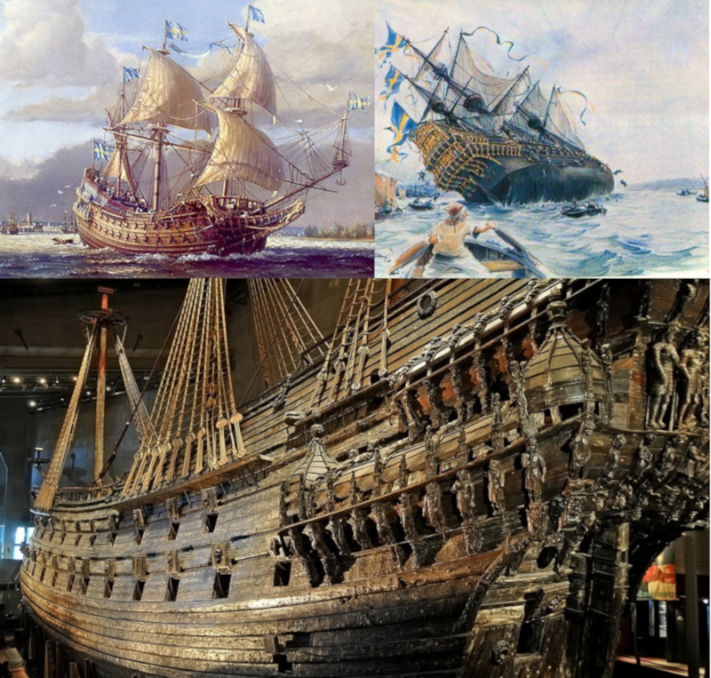
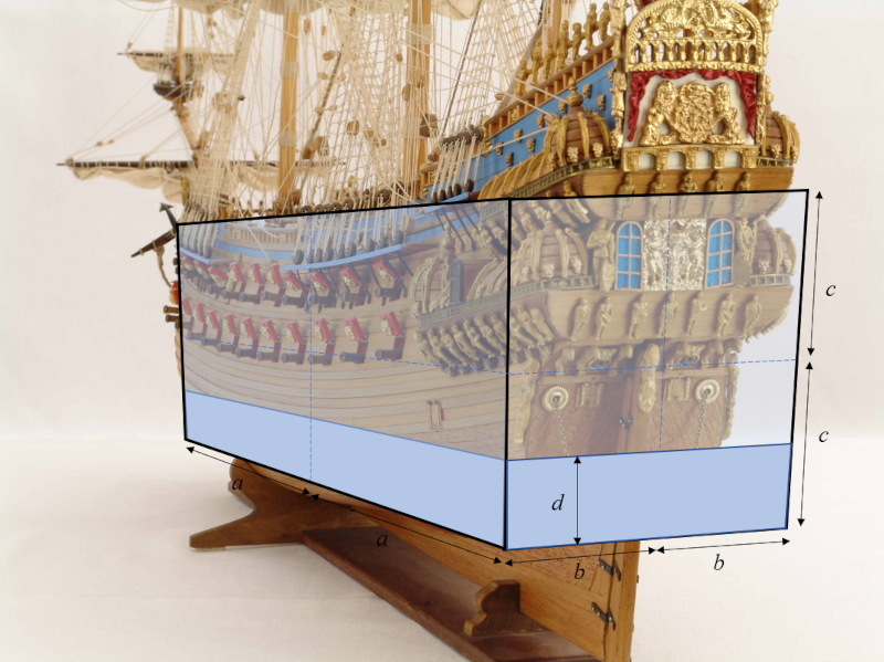
The Swedish warship Vasa is a well-known example of an unstable ship. On August 10, 1628, just 20 minutes after leaving the shipyard on its maiden voyage in Stockholm harbor, the ship capsized and sank:
The ship's design was flawed, as the narrow design was intended to achieve high speeds and the tall structure was meant to accommodate 64 cannons, a significant number. However, this design made the ship inherently unstable, leading to its capsizing with the first gust of wind.
Fortunately, the ship sank in shallow water and was preserved in the saltwater for 333 years until its recovery in 1961. Initially, the ship was kept wet, and slowly replaced the water with a mixture of wax that allowed it to be displayed completely dry in a museum just a few meters from where it sank.
The Vasa serves as a cautionary tale in shipbuilding, demonstrating the importance of careful design and stability. Its display in the museum is a popular attraction, drawing visitors from all over the world to see this remarkable piece of maritime history.
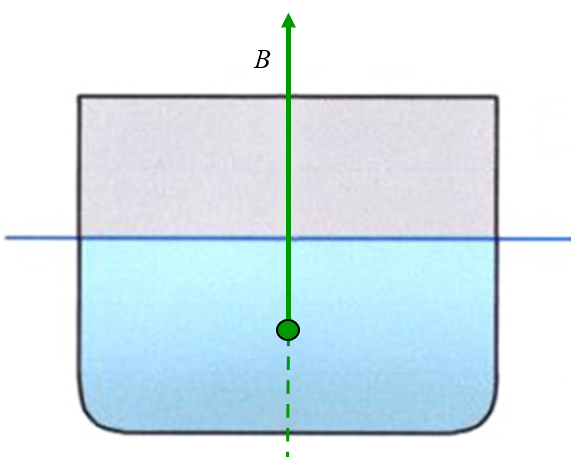
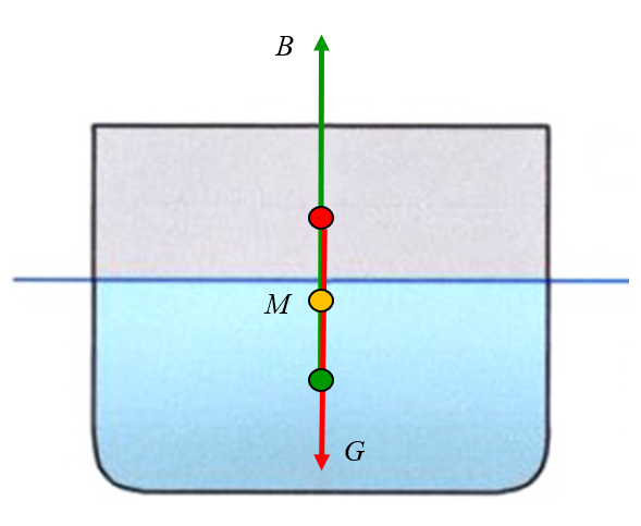
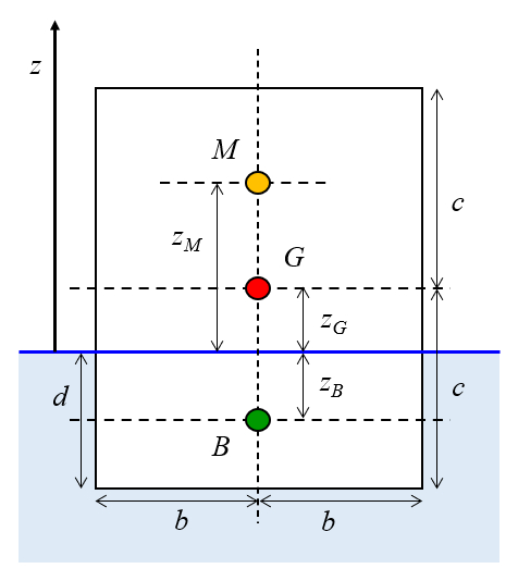
The point of application of the buoyant force is equal to the center of mass of the displaced liquid volume:
In a typical square-profiled boat, this corresponds to a point located halfway down the draft (depth of submersion).
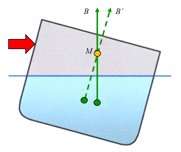
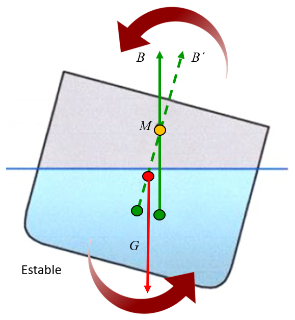
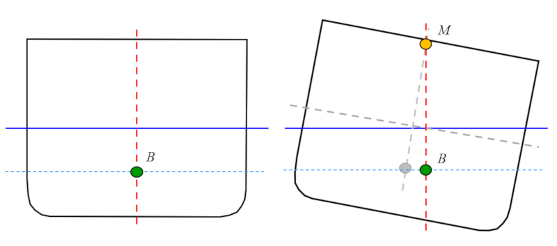
If a lateral force is applied and the object is tilted, it can be observed that the point at which the buoyancy force acts shifts away from the axis. Drawing a vertical line from this new position results in the line crossing the central axis at a point known as the metacentre:
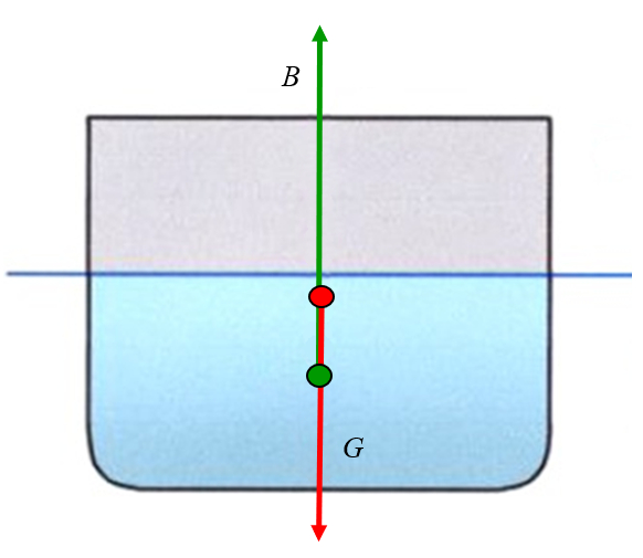
Gravity acts on the center of mass, which is usually located above the point of application of the buoyant force, but can be above or below the metacentre:
If the metacentre is located above the centre of mass, the force of gravity generates a torque that tends to stabilize the object. It is as if the object were hanging from the metacentre, and the force of gravity generates rotations around it. When the centre of mass is located below the metacentre, the torque generates a rotation towards the axis, i.e., it tends to correct the tilting, thus stabilizing the object:
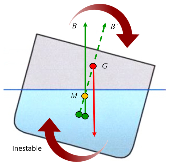
If the metacentre can be above or below the centre of gravity. The latter can easily occur if weight is added to the upper part, causing the centre of mass to rise, leading to an unstable system.
Note: to avoid losing stability, it is important to position the load in a low position (bottom of the boat).
If the metacentre is located below the centre of mass, the force of gravity generates a torque that tends to destabilize the object. It is as if the object were hanging from the metacentre, and the force of gravity generates rotations around it. When the centre of mass is located above the metacentre, the torque generates a rotation away from the axis, i.e. it tends to increase the tilt, thus destabilizing the object:
The model of the ship's hull is reduced to a parallelepiped with lengths of the medium length of the parallelepiped ($a$), the half width of the parallelepiped ($b$), and the half height of the parallelepiped ($c$), resulting in dimensions of $2a \times 2b \times 2c$, with a draft of a object draft ($d$):
A model commonly used for boats is that of a straight parallelepiped with lengths of the medium length of the parallelepiped ($a$), the half width of the parallelepiped ($b$), and the half height of the parallelepiped ($c$), and a center of mass at its geometric center. When placed in water, the body sinks to a depth of ERROR:8675.1. The position of the center where the buoyant force acts can be seen in the following image, with coordinates the bouyancy Force Attack Point Höhe ($z_B$), the height of center of mass ($z_G$), and the height of the metacenter ($z_M$):
Therefore the height of center of mass ($z_G$) is
The metacenter is calculated by determining the center of mass of the heeled body under the condition that the area below the waterline (blue line) remains constant:
When the boat is heeled, a larger section of water moves on one side and the same smaller section on the opposite side. The center of mass is therefore displaced from the center to the sector with the greatest displacement, which is calculated by
$\bar{x} = \displaystyle\frac{\displaystyle\sum_i m_i x_i}{\displaystyle\sum_i m_i}$
The mass is proportional to the section that is calculated from the half width of the parallelepiped ($b$) and the object draft ($d$) by:
$2b d$
All masses that are offset on both sides of the axis do not contribute to the numerator and only the two triangles indicated from an area with the angle of heel ($\phi$)
$b^2\phi$
weight the position of the center of mass of the triangles
$\displaystyle\frac{2b}{3}$
what is seen in the graph:
Therefore the distance from the center of mass of the water displaced from the axis is
$\displaystyle\frac{\displaystyle\frac{2b}{3} b^2\phi}{2bd}=\displaystyle\frac{b^2\phi}{3d}$
If a ship heels at the angle of heel ($\phi$), the center of mass of the displaced water moves with the half width of the parallelepiped ($b$) and the medium length of the parallelepiped ($a$) a distance of:
$\displaystyle\frac{b^2\phi}{3d}$
Since this distance is the arc of the circle that can be drawn around the metacenter, the distance between the metacenter and the center of mass of the displaced water, which corresponds to the radius, is:
$\displaystyle\frac{b^2}{3d}$
Therefore, the position of the metacenter must take into account that the coordinate center is at the height of the water surface, which is a distance $d/2$ above the center of mass of the displaced water:
with the height of the metacenter ($z_M$):
For the parallelepiped to be stable, the height of the metacenter ($z_M$) must always be greater than or equal to the height of center of mass ($z_G$), that is,
Therefore, with the height of center of mass ($z_G$) being the point of application of the given buoyancy force with the half height of the parallelepiped ($c$) and the object draft ($d$):
and the height of the metacenter ($z_M$) being with the half width of the parallelepiped ($b$):
we obtain the stability condition of a floating body ($e$):
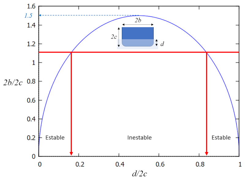
which means that there is a region in the graph $b/c$ (width/depth) versus $d/2c$ (depth/height) in which the system is stable, and in its complement, unstable:
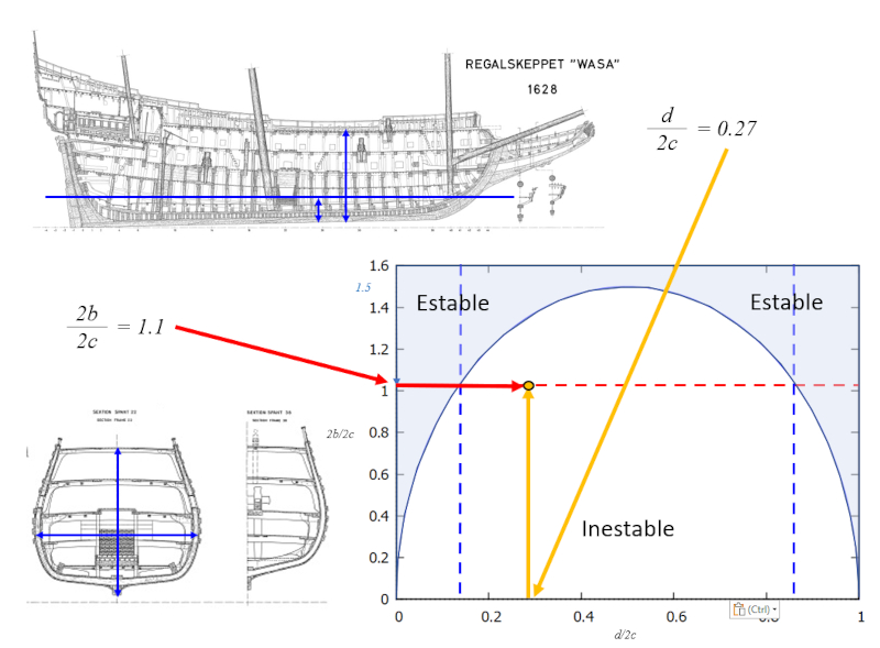
In other words, stability is achieved with large values of $b/c$ (width greater than draft). In the case of the Vasa ship, the problem was that the ship was too tall for its width. A solution would have been to 'sink it deeper', or achieve a higher $d/c$ value to avoid the zone of instability. However, this was not possible due to the openings for the cannons through which water would have entered.
For more information on build errors, see Why The Vasa Sank: 10 Problems and Some Antidotes for Software Projects, Richard E. Fairley, Mary Jane Willshire, March/April 2003 IEEE SOFTWARE, which applies to software projects.
By studying the blueprints of the Vasa, it is possible to estimate the coefficients of the ratio between the width and height, and the draft and height. This analysis reveals that the ship is unstable:
If the buoyancy force ($F_b$) and the gravitational Force ($F_g$) are equal, the object will float. In this case, it means that the mass of floating object ($M_s$) must be equal to the mass of the displaced liquid ($M_b$), resulting in:
Note: this relationship is only possible if the object 'weighs less than water', which means the displaced water occupies an equal or greater volume than the object.
The mass of floating object ($M_s$) can be calculated from the object Density ($\rho_s$) and the volume given by its geometric parameters the medium length of the parallelepiped ($a$), the half width of the parallelepiped ($b$), and the half height of the parallelepiped ($c$).
Therefore:
The mass of the displaced liquid ($M_b$) can be calculated from the liquid density ($\rho_w$) and the volume given by its geometric parameters the medium length of the parallelepiped ($a$), the half width of the parallelepiped ($b$) and the object draft ($d$).
Therefore:
The displaced volume ($V_b$) can be calculated from its geometric parameters the medium length of the parallelepiped ($a$), the half width of the parallelepiped ($b$) and the object draft ($d$).
Therefore:
The principle of Archimedes states that the mass of displaced water is equal to the mass of the object. For the specific case of the right parallelepiped, this can be expressed as the object Density ($\rho_s$), the liquid density ($\rho_w$), the object draft ($d$), and the half height of the parallelepiped ($c$) as follows:
The point of application of the buoyant force is located at the center of mass of the displaced water volume. As long as the ship is not listing, this is the center of volume at mid-depth of the draft.
Taking this into account, you can express the bouyancy Force Attack Point Höhe ($z_B$) as a function of the object draft ($d$) is:
The point of application of the gravitational force corresponds to the center of the parallelepiped modeling the hull. If we fix the coordinate system on the water surface, the height of center of mass ($z_G$) will be given by subtracting the object draft ($d$) from the half height of the parallelepiped ($c$):
The calculation of the height of the metacenter ($z_M$) from the distance between the metacenter and the center of mass of the displaced water, expressed with the half width of the parallelepiped ($b$) and the object draft ($d$), is as follows:
For the object to be stable, the height of the metacenter ($z_M$) must always be greater than or equal to the height of center of mass ($z_G$).
Therefore, it must be:
For a rectangular parallelepiped, the stability condition of a floating body ($e$) with the half width of the parallelepiped ($b$), the half height of the parallelepiped ($c$), and the object draft ($d$) is:
which is greater than one in the case of a stable situation and negative in the case of instability.
ID:(1610, 0)

