
 User:
User:


Conductors and Insulators
Storyboard

In the case of insulators, the charges do not move, which means that the material cannot be polarized. In conductors, the charges move polarizing, modifying the field. Capacitances usually have dielectric materials between the plates that are capable of biasing by increasing the capacitance.
ID:(1572, 'ky')

Electric Mobility Cargo
Description
Electrical mobility describes how easily a charged particle can move within a medium when acted upon by an external electric field. This property summarizes the dynamic balance between the acceleration produced by the field and the energy loss caused by microscopic interactions with the structure of the material.
When a Charge ($q$) is found in a Electric field ($\vec{E}$), it experiences a Electric force ($\vec{F}$):
| $\vec{F} = q \vec{E}$ |
This force accelerates the particle. In the absence of interactions, its speed would continuously increase over time. However, in real media, charged particles permanently interact with the environment that surrounds them.
Depending on the type of material, these interactions can involve collisions with atoms, thermal vibrations of the crystal lattice, impurities, structural defects, fluid molecules and other charged particles.

Each interaction transfers part of the kinetic energy of the charge to the medium. As a consequence, the continuous acceleration produced by the electric field is compensated by an average braking associated with energy dissipation.
The system then reaches a steady state where the particle no longer accelerates indefinitely, but rather acquires a constant average velocity called drift velocity.
Experimentally, it is observed that this average speed is proportional to the applied electric field:
 $\vec{v} = \mu_q \cdot \vec{E}$ $\vec{v} = \mu_q \cdot \vec{E}$
|
with Particle speed ($\vec{v}$), Electric mobility ($\mu_q$) and Electric field ($\vec{E}$).
Electric mobility then measures the capacity of the medium to allow the displacement of charges under the action of the field. A high mobility value indicates that the particles can travel relatively long distances before significantly losing energy, while a low mobility reflects strong interactions and intense braking within the medium.
Microscopically, mobility depends on how frequently collisions occur and how much they affect the motion of the particles. In very ordered and pure materials, charges can move more freely and mobility increases. In disordered, viscous or materials with many impurities, energy losses are greater and mobility decreases.
Mobility thus connects the microscopic behavior of particles with the macroscopic transport of electric current. The greater the mobility, the more efficiently the electric field can generate collective movement of charge within the material.
ID:(16292, 'gm')
Resistance Mechanism
Description
When an electric field exists, the free electrons in the material experience a force that propels them in the opposite direction to the field due to their negative charge.
Microscopically, electrons do not move freely in straight lines. As they move, atoms of the crystalline lattice, thermal vibrations, defects, impurities, microscopic boundaries between regions of the material continually interact with the internal structure of the material.
These interactions produce constant collisions and deflections in the path of the electrons. As a consequence, global movement results from a combination of acceleration caused by the electric field and braking produced by the material structure.
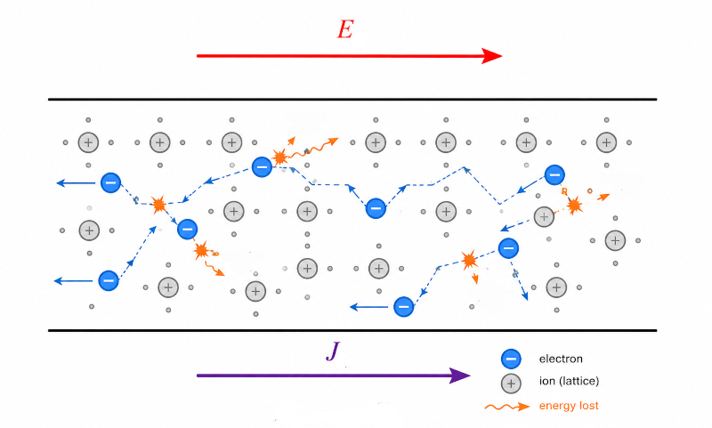
The end result is a slow, orderly average motion called drift velocity. Although each individual electron can move rapidly chaotically due to its thermal agitation, the electric field introduces a small collective tendency to move in a preferred direction.
|
$\vec{J} = \sigma \cdot \vec{E}$
|
The Driving current density ($\vec{J}$) represents precisely that net macroscopic flow of charge through the material. The greater the Electric eield ($E$) applied, the greater the average force on the electrons and the greater the current flow generated.
The proportionality constant corresponds to the Electrical conductivity ($\sigma$) of the material, which measures how easily loads can move within the structure. A material with high conductivity has electrons capable of traveling relatively long distances between collisions, while a material with low conductivity greatly hinders charge transport.
During collisions, part of the energy acquired by electrons from the electric field is transferred to the atomic lattice of the material. This energy is transformed mainly into microscopic vibrations of atoms, increasing the internal thermal energy of the body. Macroscopically this is observed as resistive heating or Joule effect.
Therefore, electrical conduction in real materials does not correspond to a free movement without losses, but to a dynamic process where the electric field continuously delivers energy to the charges and they progressively dissipate it in the microscopic structure of the material.
ID:(11763, 'gm')
Load Flow Density
Description
Charge flux density describes how much electrical charge passes through a surface per unit time and per unit area. To determine it, a set of charged particles distributed within a volume and moving with an average speed under the action of an electric field is considered.
Assume a medium containing a uniform concentration of charged particles. If the particles have an average drift velocity, during a small time interval they will advance a certain distance in the direction of motion. As a consequence, all the particles contained in a sheet of the swept volume will pass through the considered surface.
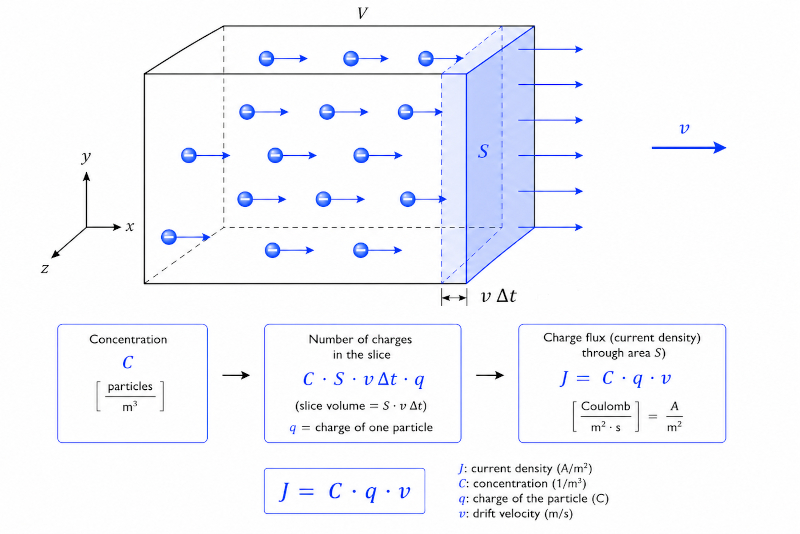
The volume transported during that interval corresponds to the surface area multiplied by the distance traveled by the particles. If the concentration of particles per unit volume is known, it can be calculated how many particles cross the surface in that time.
By then multiplying the number of particles by the individual charge of each one, the total amount of charge transported is obtained. Finally, dividing by area and time gives the current density or charge flux density.
The result leads to:
|
$\vec{J} = C_n \cdot q \cdot \vec{v}$
|
with Driving current density ($\vec{J}$), Charge concentration ($C_n$), Charge ($q$) and Particle speed ($\vec{v}$).
The equation shows that the current density increases when there are more particles available to carry charge, each particle has a greater charge, or the particles move more quickly within the medium.
This relationship directly connects the microscopic behavior of charged particles to the macroscopic transport of electric current observed in conductors, plasmas, electrolytes, and other material media.
ID:(16293, 'gm')
Electrical Conductivity
Description
From the definition of Driving current density ($\vec{J}$) based on Charge concentration ($C_n$), Charge ($q$) and Particle speed ($\vec{v}$):
and as with Electric mobility ($\mu_q$) and Electric field ($\vec{E}$):
you have to have the relationship with Electrical conductivity ($\sigma$)
let us conclude that
ID:(16291, 'gm')
Material Polarization
Description
When an insulating material is subjected to an external electric field, its internal charges respond by reorganizing microscopically. Negative charges tend to move slightly in the opposite direction of the field, while positive charges move slightly in the direction of the field. Since both remain linked within atoms or molecules, complete charge separation and free flow do not occur as in a conductor.
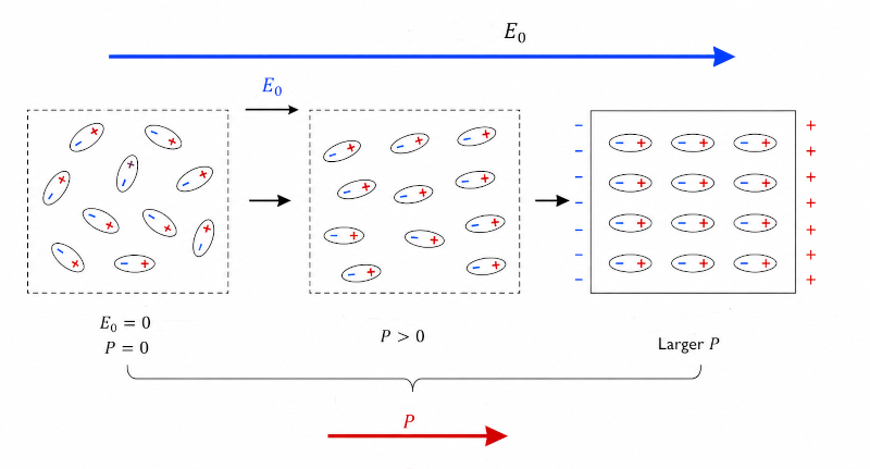
The result is the formation or reorientation of small electrical dipoles distributed in the material. In the absence of an external field, these dipoles are usually oriented randomly, so that their effects compensate each other and there is no appreciable macroscopic polarization.
By applying an electric field, the material begins to develop a preferred orientation. The greater the applied field, the greater the tendency for the dipoles to align collectively. This partial orientation produces a net polarization of the material, that is, an average effective separation between positive and negative charges within the volume.
Polarization generates bound charges on the surfaces of the material and produces an internal induced field that partially opposes the applied field. However, because the charges remain microscopically bound, the field does not completely cancel out and continues to penetrate the dielectric.
In many insulating materials, especially for moderate fields, it is experimentally observed that Dipole moment ($\vec{P}$) increases approximately proportionally to the applied Electric eield ($E$). The proportionality constant depends on the material's ability to deform or orient its internal dipoles under the action of the field. By entering Electrical susceptibility ($\chi_e$) and Electric field constant ($\epsilon_0$) you can calculate Dipole moment ($\vec{P}$) using:
|
$\vec{P} = \epsilon_0 \cdot \chi_e \cdot \vec{E}$
|
Electrical susceptibility measures how easily the material can become polarized. A large value indicates that the internal dipoles respond strongly to the external field, while a small value reflects a weaker polarizable response.
Vacuum permittivity represents the fundamental ability of empty space to allow the existence of an electric field and store electrical energy associated with it. It acts as the basic constant that sets the natural scale of electrical interactions in electromagnetism.
ID:(11764, 'gm')
Electric displacement
Description
The concept of electrical displacement arises when studying how a dielectric material responds when subjected to an external electric field. In a vacuum, the electric field is determined only by the free charges present. However, within an insulating material an internal reorganization of bound charges also appears due to the polarization of the medium.
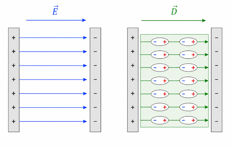
This means that the total electric field within the material no longer comes only from the external applied charges, but also from the dipoles induced inside the dielectric. As a consequence, directly separating the effects of free charges and internal polarization can become complex.
The Electric displacement ($\vec{D}$) is introduced precisely to describe more simply how free charges generate electric fields in the presence of polarizable materials. Instead of working only with the total electric field, a new magnitude is defined that automatically incorporates the contribution of the polarization of the medium.
The magnitude is defined by
|
$\vec{D} = \epsilon_0 \cdot \vec{E} + \vec{P}$
|
with Electric field constant ($\epsilon_0$), Electric field ($\vec{E}$) and Dipole moment ($\vec{P}$).
Electrical displacement can be physically interpreted as a measure of how much effective electrical flux passes through the medium due to free charges, automatically considering how the material internally modifies the field through polarization.
ID:(16030, 'gm')
Displacement and Electric Field
Description
How Dipole moment ($\vec{P}$) depends in the static case on Electric field ($\vec{E}$) within the calculation of Electric displacement ($\vec{D}$)
| $\vec{D} = \epsilon_0 \cdot \vec{E} + \vec{P}$ |
with Electric field constant ($\epsilon_0$) and Electrical susceptibility ($\chi_e$) so you can enter the constant Relative permittivity of the material ($\epsilon_r$) such that
|
$\vec{D} = \epsilon_r \cdot \vec{E}$
|
ID:(16294, 'gm')
Relative permittivity of the material
Description
Since Electric displacement ($\vec{D}$), considering Electric field ($\vec{E}$), Dipole moment ($\vec{P}$) and Electric field constant ($\epsilon_0$), can be expressed as:
and that Dipole moment ($\vec{P}$), depending on Electrical susceptibility ($\chi_e$), results:
is obtained for Relative permittivity of the material ($\epsilon_r$), using:
the relationship:
ID:(16295, 'gm')
Conductors and Insulators
Description

Calculations
to  ,
then, select the variable:
,
then, select the variable:  to
to 
Calculations
Variable
 Given
Calculate
Given
Calculate
 Target :
Equation
To be used
Target :
Equation
To be used

Variables
ID:(1572, 0)
Palos Verdes, Costa de Corral, Chile