
Parallel hydraulic elements
Storyboard 
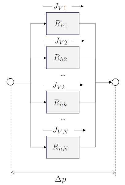
When hydraulic elements are connected in parallel, the flow is distributed among them, while the pressure drop is the same for all of them. The sum of the individual flows results in the total flow, and therefore, the total hydraulic resistance is equal to the inverse of the sum of the inverses of the individual hydraulic resistances. On the other hand, hydraulic conductivities are summed directly.
ID:(1467, 0)
Hydraulic conductance of elements in parallel
Concept
En el caso de una suma en la que los elementos están conectados en paralelo, la conductancia hidráulica total del sistema se calcula sumando las conductancias individuales de cada elemento.
With the total flow ($J_{Vt}$) being equal to the volume flow in a network ($J_{Vk}$):
| $ J_{Vt} =\displaystyle\sum_k J_{Vk} $ |
and with the pressure difference ($\Delta p$) and the hydraulic conductance in a network ($G_{hk}$), along with the equation
| $ J_{Vk} = G_{hk} \Delta p $ |
for each element, it leads us to the conclusion that with the parallel total hydraulic conductance ($G_{pt}$),
$J_{Vt}=\displaystyle\sum_k J_{Vk} = \displaystyle\sum_k G_{hk}\Delta p = G_{pt}\Delta p$
we have
| $ G_{pt} =\displaystyle\sum_k G_{hk} $ |
ID:(12800, 0)
Hydraulic resistance of elements in parallel
Concept
In the case of a sum where the elements are connected in parallel, the total hydraulic resistance of the system is calculated by adding the individual resistances of each element.
the parallel total hydraulic conductance ($G_{pt}$) combined with the hydraulic conductance in a network ($G_{hk}$) in
| $ G_{pt} =\displaystyle\sum_k G_{hk} $ |
and along with the hydraulic resistance in a network ($R_{hk}$) and the equation
| $ R_{hk} = \displaystyle\frac{1}{ G_{hk} }$ |
leads to the total hydraulic resistance in parallel ($R_{pt}$) via
| $\displaystyle\frac{1}{ R_{pt} }=\sum_k\displaystyle\frac{1}{ R_{hk} }$ |
ID:(11068, 0)
Process for the addition of hydraulic resistances in parallel
Description
First, values for the hydraulic resistance in a network ($R_{hk}$) are calculated using the variables the viscosity ($\eta$), the cylinder k radio ($R_k$), and the tube k length ($\Delta L_k$) through the following equation:
| $ R_{hk} =\displaystyle\frac{8 \eta | \Delta L_k | }{ \pi R_k ^4}$ |
These values are then summed to obtain the total hydraulic resistance in series ($R_{st}$):
| $\displaystyle\frac{1}{ R_{pt} }=\sum_k\displaystyle\frac{1}{ R_{hk} }$ |
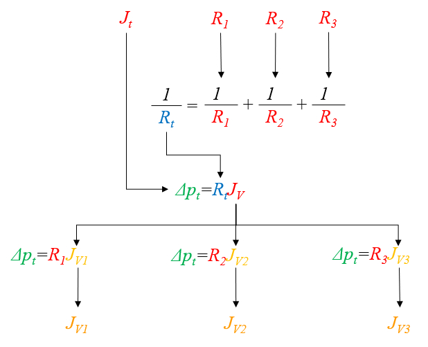
With this result, it is possible to calculate the variación de la Presión ($\Delta p$) for the total hydraulic resistance in parallel ($R_{pt}$) using:
| $ \Delta p = R_h J_V $ |
Once the variación de la Presión ($\Delta p$) is determined, the volume flow in a network ($J_{Vk}$) is calculated via:
| $ \Delta p = R_h J_V $ |
For the case of three resistances, the calculations can be visualized in the following chart:
ID:(11070, 0)
Parallel hydraulic elements
Model
When hydraulic elements are connected in parallel, the flow is distributed among them, while the pressure drop is the same for all of them. The sum of the individual flows results in the total flow, and therefore, the total hydraulic resistance is equal to the inverse of the sum of the inverses of the individual hydraulic resistances. On the other hand, hydraulic conductivities are summed directly.
Variables
Calculations
Calculations
Equations
The volume flow ($J_V$) can be calculated from the hydraulic conductance ($G_h$) and the pressure difference ($\Delta p$) using the following equation:
| $ J_V = G_h \Delta p $ |
Furthermore, using the relationship for the hydraulic resistance ($R_h$):
| $ R_h = \displaystyle\frac{1}{ G_h }$ |
results in:
| $ \Delta p = R_h J_V $ |
(ID 3179)
The parallel total hydraulic conductance ($G_{pt}$) combined with the hydraulic conductance in a network ($G_{hk}$) in
| $ G_{pt} =\displaystyle\sum_k G_{hk} $ |
and along with the hydraulic resistance in a network ($R_{hk}$) and the equation
| $ R_{hk} = \displaystyle\frac{1}{ G_{hk} }$ |
leads to the total hydraulic resistance in parallel ($R_{pt}$) via
| $\displaystyle\frac{1}{ R_{pt} }=\sum_k\displaystyle\frac{1}{ R_{hk} }$ |
(ID 3181)
Since the hydraulic resistance ($R_h$) is equal to the hydraulic conductance ($G_h$) as per the following equation:
| $ R_h = \displaystyle\frac{1}{ G_h }$ |
and since the hydraulic conductance ($G_h$) is expressed in terms of the viscosity ($\eta$), the tube radius ($R$), and the tube length ($\Delta L$) as follows:
| $ G_{hk} =\displaystyle\frac{ \pi R_k ^4}{8 \eta | \Delta L_k | }$ |
we can conclude that:
| $ R_h =\displaystyle\frac{8 \eta | \Delta L | }{ \pi R ^4}$ |
(ID 3629)
With the total flow ($J_{Vt}$) being equal to the volume flow in a network ($J_{Vk}$):
| $ J_{Vt} =\displaystyle\sum_k J_{Vk} $ |
and with the pressure difference ($\Delta p$) and the hydraulic conductance in a network ($G_{hk}$), along with the equation
| $ J_{Vk} = G_{hk} \Delta p $ |
for each element, it leads us to the conclusion that with the parallel total hydraulic conductance ($G_{pt}$),
$J_{Vt}=\displaystyle\sum_k J_{Vk} = \displaystyle\sum_k G_{hk}\Delta p = G_{pt}\Delta p$
we have
| $ G_{pt} =\displaystyle\sum_k G_{hk} $ |
.
(ID 3634)
If we examine the Hagen-Poiseuille law, which allows us to calculate the volume flow ($J_V$) from the tube radius ($R$), the viscosity ($\eta$), the tube length ($\Delta L$), and the pressure difference ($\Delta p$):
| $ J_V =-\displaystyle\frac{ \pi R ^4}{8 \eta }\displaystyle\frac{ \Delta p }{ \Delta L }$ |
we can introduce the hydraulic conductance ($G_h$), defined in terms of the tube length ($\Delta L$), the tube radius ($R$), and the viscosity ($\eta$), as follows:
| $ G_{hk} =\displaystyle\frac{ \pi R_k ^4}{8 \eta | \Delta L_k | }$ |
to arrive at:
| $ J_V = G_h \Delta p $ |
(ID 14471)
Examples
(ID 15726)
One efficient way to model a tube with varying cross-sections is to divide it into sections with constant radii and then sum the hydraulic resistances in series. Suppose we have a series of elements the hydraulic resistance in a network ($R_{hk}$), whose resistance depends on the viscosity ($\eta$), the cylinder k radio ($R_k$), and the tube k length ($\Delta L_k$), according to the following equation:
| $ R_{hk} =\displaystyle\frac{8 \eta | \Delta L_k | }{ \pi R_k ^4}$ |
In each element, we consider a pressure difference in a network ($\Delta p_k$) along with the hydraulic resistance in a network ($R_{hk}$) and the volumetric flow rate the volume flow ($J_V$), where Darcy's law is applied:
| $ \Delta p = R_h J_V $ |
The total resistance of the system, the flujo de Volumen Total ($J_{Vt}$), is equal to the sum of the individual hydraulic resistances ERROR:10133,0 of each section:
| $ J_{Vt} =\displaystyle\sum_k J_{Vk} $ |
Thus, we have:
$J_{Vt}=\displaystyle\sum_k \Delta J_{Vk}=\displaystyle\sum_k \displaystyle\frac{\Delta p_k}{R_{hk}}=\left(\displaystyle\sum_k \displaystyle\frac{1}{R_{hk}}\right)\Delta p\equiv \displaystyle\frac{1}{R_{pt}}J_V$
Therefore, the system can be modeled as a single conduit with a total hydraulic resistance calculated by summing the individual components:
| $\displaystyle\frac{1}{ R_{pt} }=\sum_k\displaystyle\frac{1}{ R_{hk} }$ |
(ID 11068)
In the case of a sum where the elements are connected in series, the total hydraulic conductance of the system is calculated by adding the individual hydraulic conductances of each element.
the total hydraulic resistance in parallel ($R_{pt}$), along with the hydraulic resistance in a network ($R_{hk}$), in
| $\displaystyle\frac{1}{ R_{pt} }=\sum_k\displaystyle\frac{1}{ R_{hk} }$ |
and along with the hydraulic conductance in a network ($G_{hk}$) and the equation
| $ R_{hk} = \displaystyle\frac{1}{ G_{hk} }$ |
leads to the parallel total hydraulic conductance ($G_{pt}$) can be calculated with:
| $ G_{pt} =\displaystyle\sum_k G_{hk} $ |
(ID 15946)
First, values for the hydraulic resistance in a network ($R_{hk}$) are calculated using the variables the viscosity ($\eta$), the cylinder k radio ($R_k$), and the tube k length ($\Delta L_k$) through the following equation:
| $ R_{hk} =\displaystyle\frac{8 \eta | \Delta L_k | }{ \pi R_k ^4}$ |
These values are then summed to obtain the total hydraulic resistance in series ($R_{st}$):
| $\displaystyle\frac{1}{ R_{pt} }=\sum_k\displaystyle\frac{1}{ R_{hk} }$ |
With this result, it is possible to calculate the variación de la Presión ($\Delta p$) for the total hydraulic resistance in parallel ($R_{pt}$) using:
| $ \Delta p = R_h J_V $ |
Once the variación de la Presión ($\Delta p$) is determined, the volume flow in a network ($J_{Vk}$) is calculated via:
| $ \Delta p = R_h J_V $ |
For the case of three resistances, the calculations can be visualized in the following chart:
(ID 11070)
(ID 15731)
ID:(1467, 0)